3.2.11 Input and Output Pins
The Input and Output Pins tab informs of the pin states and settings.
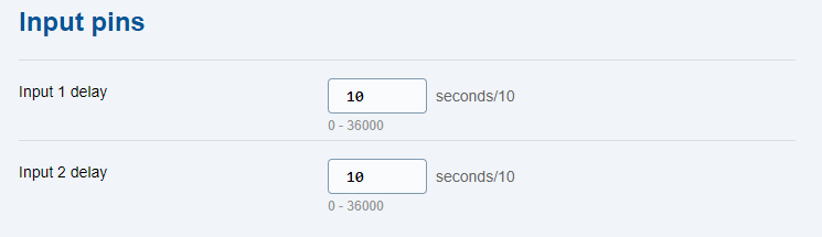 |
- Input 1&2 delay – protective period (in tenths of a second) during which the pin state change should last until the change is detected on the input pin.
Note
- The input activation generates an event: Input X high.
- The input deactivation generates an event: Input X low.
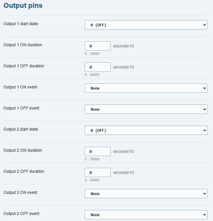 |
Upon the 2N® LiftGate power up / restart, the states of the two outputs are OFF and switch to ON in a few seconds (after the system start up is completed) if configured so. If the Duration parameter is set to 0, the required ON / OFF state will be permanent, otherwise the required state holds as set in the Duration parameter and then switches back. In case the Event parameter is set to a valid value, the output closes / opens whenever the set event occurs.
The output states can also be controlled using SMS or HTTP commands.
- Output 1, 2 start state – initial output state at system power up.
- Output 1,2 ON duration – ON state duration (in tenths of a second).
- Output 1,2 OFF duration – OFF state duration (in tenths of a second).
- Output 1,2 ON event – event that initiates a state change to ON.
- Output 1,2 OFF event – event that initiates a state change to OFF.