2.13 Camera Module
Description
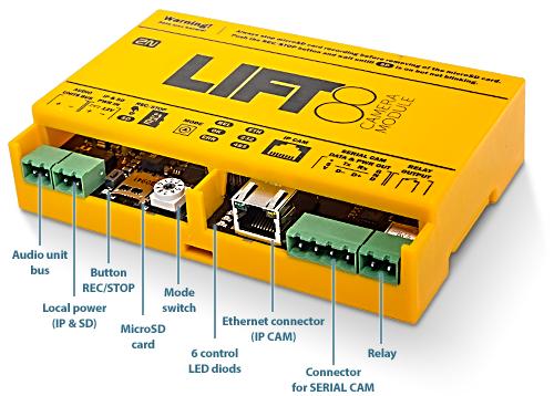
The camera module helps you connect a lift cabin camera of the IP, RS-232 and RS-485 type. The camera module can work with the Central Unit (CU), or autonomously. It contains a microSD card slot for recording images in variable intervals.
 |
Connect the camera module to the CU or splitter via a 2-wire bus to support the 2N® Lift8 communication.
Connect a local power supply to record images on the microSD card.
Caution - upgrade
- The red ERR LED is illuminated, the green OK LED flashes quickly and the yellow REL LED flashes slowly to indicate the upgrading process.
Caution
- Local power is supported.
- Connect the local power supply if:
- an IP camera communicating with the CU is connected to the camera module;
- images are recorded on the microSD card in certain intervals;
- the camera module works autonomously without bus connection.
Electric Installation
Bus Connection
Connect the camera module via a 2-wire bus (audio unit bus) to the CU or splitter maintaining polarity.
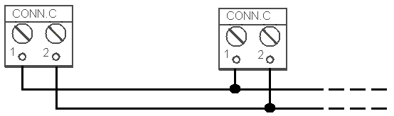 |
| Audio unit bus |
|---|
| 1... Audio unit bus + |
| 2... Audio unit bus – |
Warning
- Maintain the connection polarity to make the 2N® Lift8 system work correctly.
Safety
- The bus is electrically isolated from the telephone line circuits according to the EN60950 requirements and its low voltage cannot cause any electrical accident.
Mode Switch
Set the camera module connection mode with a 10-position switch 0–9:
0 – the camera module works within the 2N® Lift8 system (connected to the CU/splitter via a 2-wire bus);
1 – the camera module works autonomously (see below for details);
2–9 – no setting (the red ERR LED is flashing).
IP Camera Connection
There are two IP camera connection options.
- Connect the IP camera directly to the camera module.
- Connect the camera module to the LAN if the IP camera is installed in the LAN.
If the camera module is connected to the Lift8 system, use the Service Tool for configuration (refer to Subs. 5.3 – Service Tool – Use for more details).
Refer to the Autonomous Camera Module Connection Subs. for more setting details.
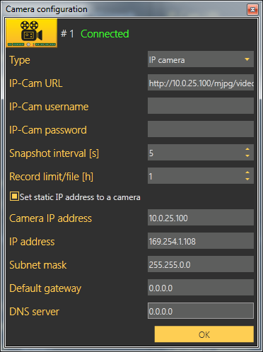
Direct IP camera - camera module connection
 |
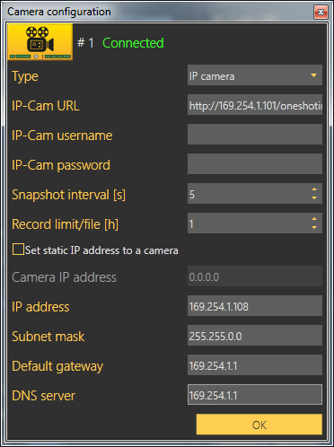
IP camera LAN connection
 |
Select Set static IP address to a camera to activate the DHCP server to assign the defined address to the camera. If the static IP address is already set for the IP camera, it is unnecessary to enable the server.
Caution
- To retrieve the IP address from the DHCP server, make sure that the Retrieve IP address from DHCP server option is enabled for the camera.
- Switch on the local power supply.
RS-232/RS-485 Camera Connection
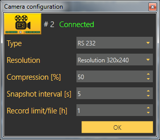
Set only the resolution, compression, snapshot interval and Record limit/file parameters for the RS232 and RS485 cameras.
 |
Connect the camera to the SERIAL CAM connector using a push-on terminal board.
See the table below for connector details.
| +5 V | TX/D | RX/D+ | GND |
|---|---|---|---|
| +UCC | data transmitted | data received | signal ground |
Caution
- The RS232 and RS485 cameras work without a local power supply too in the Lift8 system only if they have a low current consumption.
- Saving files to an SD card does not work without a local power supply.
Tip
We recommend you to switch on a local power supply because cameras usually take more current in the night mode (for infrared illumination).
LED Indicators
The camera module is equipped with seven LED indicators; see the table below.
| Name | Colour | Description |
|---|---|---|
| SD | Orange | The LED flashes to indicate recording. However, the camera type must flash at the same time (ETH, 232, 485). When the LED is on, you can slide the microSD card out by pressing the REC/STOP button. |
| REL | Orange | The LED is illuminated to indicate a closed relay. |
OK | Green | The LED flashes (slowly) to indicate that the bus is connected and the camera module is communicating with the CU. The LED flashes (quickly) to indicate image download. The LED is illuminated permanently to indicate that the module is connected in the autonomous mode and is OK. |
ERR | Red | The LED flashes to indicate an error in the camera module or Ethernet cable connection. The LED is illuminated to indicate address collision. Make sure that one camera module is only connected in the shaft. |
ETH | Orange | The LED is on when the camera is connected and configured properly. The LED flashes to indicate active recording. |
232 | Orange | The LED is on when the camera is connected and configured properly. The LED flashes to indicate active recording. |
| 485 | Orange | The LED is on when the camera is connected and configured properly. The LED flashes to indicate active recording. |
Caution
- The OK LED is flashing and ERR LED is illuminated when the unit is being upgraded.
Caution
- Use the 2N® Lift8 Service Tool application to set the camera type and other parameters.
Camera Module Setting
Set the 2N® Lift8 camera module via the 2N® Lift8 Service Tool. Refer to 5.3 Use for details.
Autonomous Camera Module Connection
There are two IP camera connection options.
- Connect the IP camera directly with the camera module.
- Connect the camera module to the LAN if the IP camera is installed in the LAN.
Caution
- You are recommended to format the microSD card before inserting it in the camera module (FAT32).
- You are recommended to connect the camera module to a backup power supply to avoid recording errors at power outage. Connect the IP camera to the backup power supply too.
Camera Module Settings (network.cfg)
| Parameter name | Default value | Note |
|---|---|---|
| IP address | 10.0.0.254 | Camera module IP address |
| Gateway | 0.0.0.0 | Gateway IP address |
| DNS | 0.0.0.0 | DNS server IP address |
| Netmask | 255.0.0.0 | Network mask |
DHCP camera ip address | 0.0.0.0 | 0.0.0.0 = disabled Ip address = DHCP server enabled on camera module. Used only if the IP camera is directly connected with the camera module. |
Caution
- Set Camera IP address to enable the DHCP server and assign the selected address to the IP camera. Make sure that the Retrieve IP address from DHCP server option is enabled for the camera.
- Refer to network.cfg for more setting details.
- Having set the network parameters, you can open the Internet browser to go on configuring via the web interface (see the Web Interface below).
IP Camera Settings (camera.cfg)
| Parameter name | Value range | Default value | Note |
|---|---|---|---|
Camera type | 1–3 | 3 | 1 = RS-232 2 = RS-485 3 = IP camera |
Resolution | 1–3 | 2 | 1 = 160 x 80 2 = 320 x 240 3 = 640 x 480 |
| Compression ratio | 10–100 % | 60 % | Image compression |
| Camera URL IP | http://10.0.0.1/jpg/image.jpg | Each camera has a different URL. | |
| Record interval | 1–3600 s | 5 s | Camera recording interval |
Record rotate file interval [1h] | 1–24h | 1 h | MicroSD card file creation interval |
| Username | admin | IP camera access user name (login) | |
| Password | 2n | IP camera access password |
Caution - IP camera
- Set resolution and compression in your IP camera configuration.
- Each IP camera has a different URL.
Caution
- Refer to camera.cfg for more setting details.
Date and Time Settings (time.cfg)
| Parameter name | Default value | Note |
|---|---|---|
| Coordinated Universal Time | 0 | Set the time zone in which the camera module is located. |
| Date (dd:mm:yyyy) | 01.01.1970 | |
| Time (hh:mm:ss) | 00:00:00 |
Caution
- Refer to time.cfg for more setting details.
Password Setting (password.cfg)
| Parameter name | Default value | Note |
|---|---|---|
| password | 2n | The password set via password.cfg is encrypted when an SD card is inserted in the camera module. |
Upozornění
- The user name is always Admin (not respecting the upper/lower case).
Standalone Camera Module Upgrade
Refer to 2N® Lift8 Camera Module at www.2n.cz for the latest firmware (ln_app_camera.bin). Download the file to a microSD root directory. When you insert the microSD card, the file (ln_app_camera.bin) will be loaded onto the dataflash (yellow LEDs flashing) and then the module will get restarted. Upon restart, the new FW will be loaded to the camera module. The ln_app_camera.bin file will be renamed to OFF_ln_app_camera.bin.
MicroSD Card
Insert the microSD card in the slot. If the card is loaded correctly and the camera module is configured properly, the orange SD LED will start flashing to indicate that images are recorded onto the microSD card in the selected intervals. Press REC/STOP to remove the microSD card and wait until the LED stops flashing.
Caution
- Support of microSD cards up to 32 GB.
- Saving files to an SD card does not work without a local power supply.
Web Interface
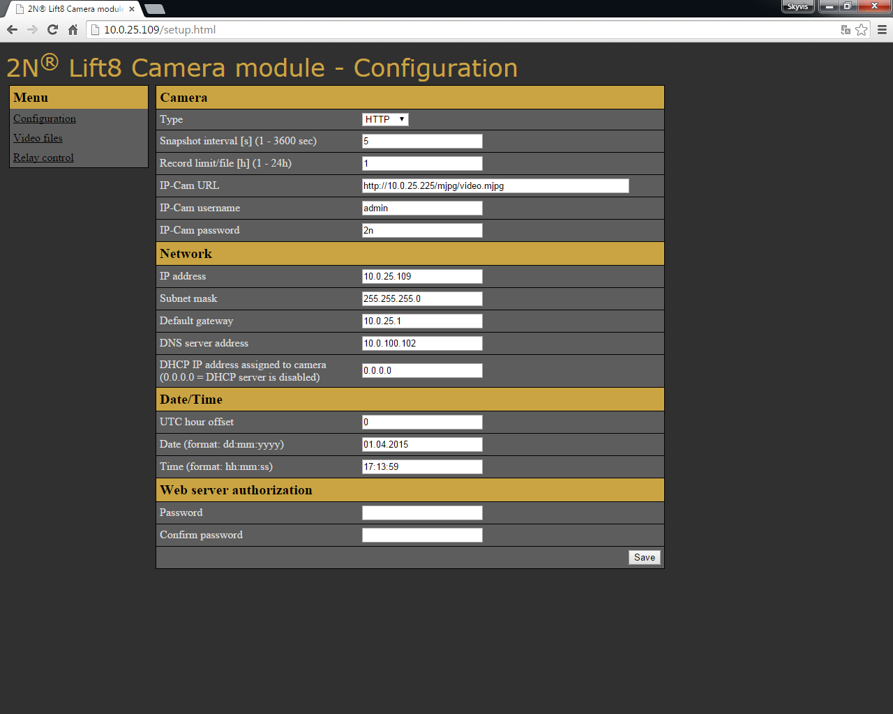
Enter the camera module IP address into the Internet browser to display the camera module web menu in English.
There are 3 menus:
- Configuration – set the same camera module (available in the autonomous mode only) parameters as in the SD card files (camera.cfg, network.cfg, password.cfg and time.cfg).
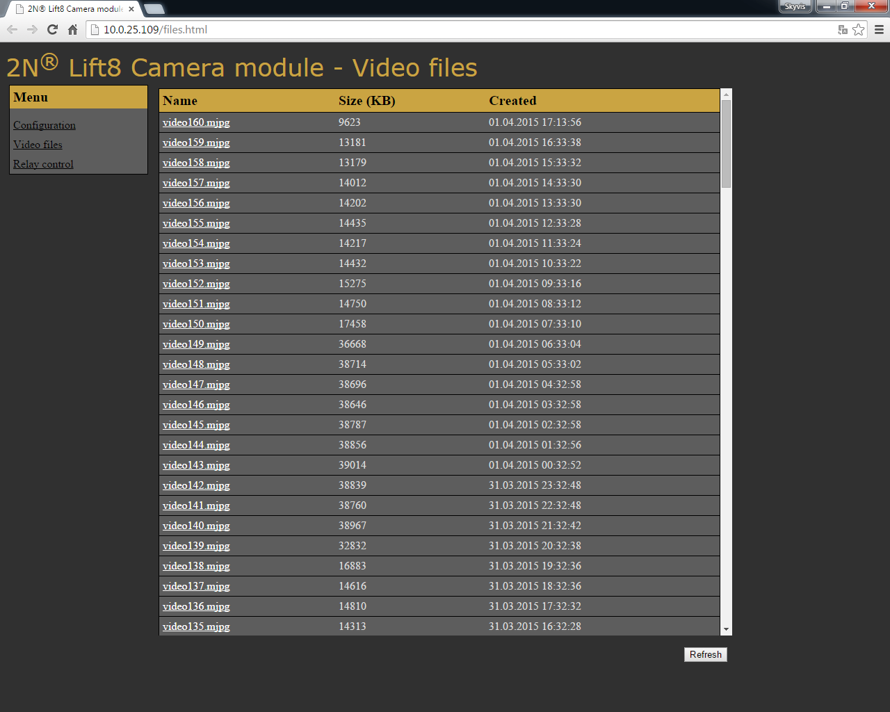
- Video files – display the video files recorded.
- Relay control – set the camera module relay control.
 |
 |
User name: Admin
Password: 2n
Caution
- You can only change the web access password via the web and password.cfg. The username is always the same (Admin, regardless of lower/upper case).
- If the RS232 and RS485 cameras are connected, you cannot get connected to the camera module web interface.
Tip
Download the recorded files in the Video files section. As the download rate is very slow, you are recommended to remove the SD card and load the files directly from the card to get the files more quickly.
Relay Control HTTP Commands
You can also use http commands to close/open the relay.
| Function | HTTP command |
|---|---|
| Relay state | http://10.0.0.1/relay_get |
| Close relay | http://10.0.0.1/relay_set?value=1 |
| Open relay | http://10.0.0.1/relay_set?value= 0 |
Mounting Types
See below for the mounting types and necessary components. Install the device on sites not exposed to water leakage or condensation.
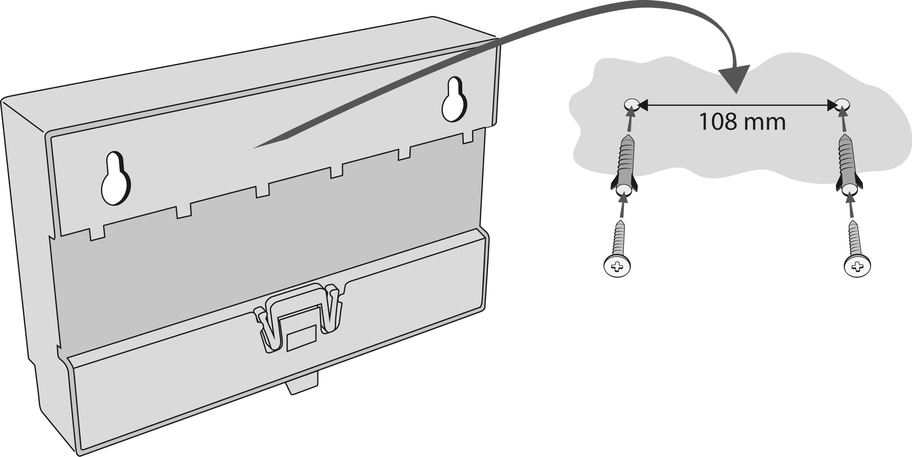
Wall Mounting
Use appropriate wall plugs and screws for mounting (not included in the delivery). Hang the device using the pre-drilled holes on the device bottom.
 |
Wall Mounting
DIN Rail Mounting
Mount the device on a standard TS 35 DIN rail. The recommended DIN rail length is 14 cm.
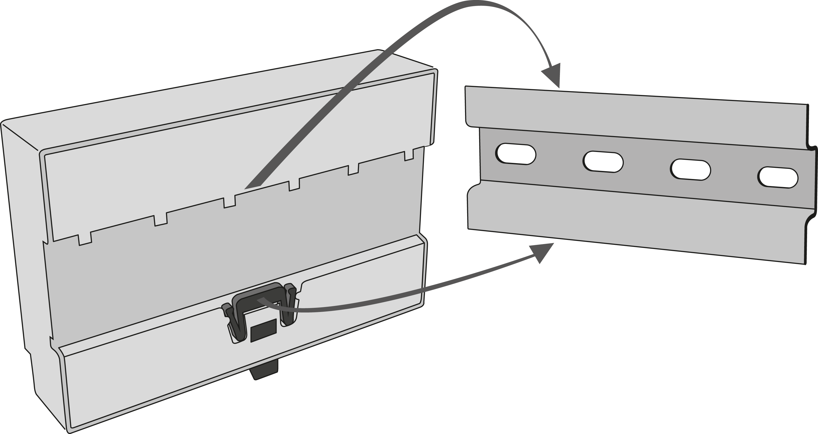 |
DIN Rail Mounting
Caution
- The warranty does not cover any defects or failures of the product arisen as a result of improper mounting in contradiction to these instructions.
- A wrong mounting procedure may lead to damage to the electronics due to water infiltration. The Camera Module circuits are under constant voltage and water leakage causes electrochemical reaction. No warranty can be claimed for products damaged in this manner!