2.12 I/O Module
Description
The purpose of the I/O Module is to interconnect the Central Unit (CU) with the lift signalling. It is designed for usage of binary inputs or switching of relay inputs. It is connected to the CU via 6 wires (power, audio, data). The inputs/outputs are connected to the I/O Module via 2-pin slide-on terminals.
The I/O Module detects status changes on 4 galvanically isolated logical inputs, whose nominal voltage ranges between 12 and 24V AC/DC (refer to the table below for the minimum and maximum voltage values). The I/O Module also contains 4 output NO contacts equipped with bistable relays (refer to the table below for the maximum closing values). There may be up to 8 I/O Modules (depending on the count of lift shafts available).
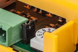
Remember to set a different address (lift shaft number) for each I/O Module to make the system work properly. A collision of addresses is signalled by the ERR LED. Set the address manually using the rotary switch (position 1–8 according to lift shaft 1–8). Addresses 9 and 0 are not used. If you set one of them, the ERR LED will indicate an error.
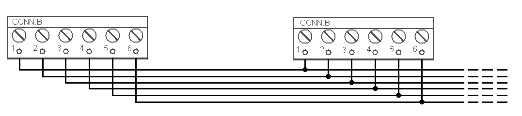
The I/O Modules are connected serially (in line). Do not use parallel connection to avoid system instability. Connect the termination resistance connecting jumper to the last device (Splitter or I/O Module furthest from the CU). See the figures below for terminal layout details.
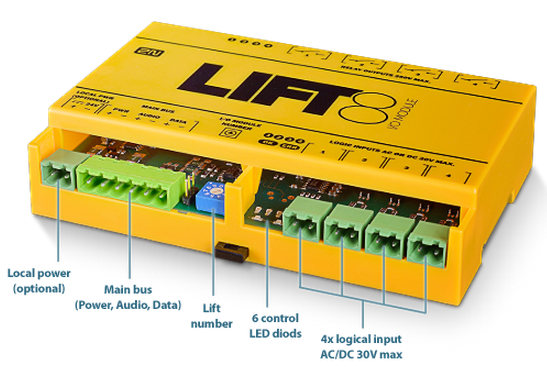 |
I/O Module – Lower Side
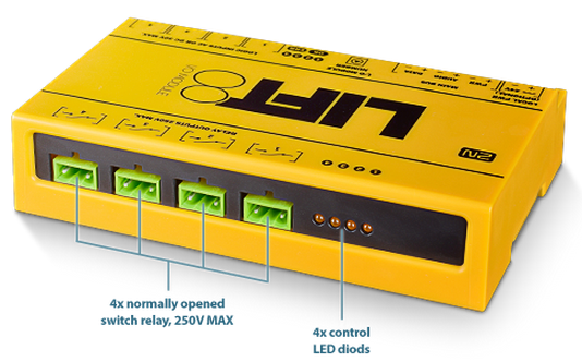 |
I/O Module – Upper Side
Electrical Installation
Caution
- Local power is not supported. Do not connect any local power supply.
- The main bus power is sufficient for the I/O Module.
Main Bus Connection
Take the 6-pin main bus connector from the package and connect 6 wires from the CU maintaining polarity (power + -, audio + -, data + - ) – see the I/O Module cover. Connect the devices serially (in line). Parallel connection is not allowed. Refer to the CU section for more details.
 |
| Main bus |
| 1 … Main bus power + |
| 2 … Main bus power - |
| 3 … Main bus audio + |
| 4 … Main bus audio - |
| 5 … Main bus data + |
| 6 … Main bus data - |
Warning
- Maintain the connection polarity to make the 2N® Lift8 system work correctly.
Warning
- The bus is electrically isolated from the telephone line circuits according to the EN60950 requirements and its low voltage cannot cause any electrical accident.
Termination Resistance
Caution
- Find the 3-pin termination resistance connecting jumper between the main bus connector and lift number switch.
- Connect the jumper to the first and last device (CU, splitter or I/O module) on the bus. Refer to the CU section for more details.
- By default, the termination resistance jumper is off.
 |
Termination Resistance Off
Address Setting
Use a 10-pin rotary switch 0–9 (see the figure above) to set the I/O Module address for a lift. Set 1–8 like the shaft number for the splitter (set 5 for lift 5, e.g.).
Warning
- Do not set address 0 and 9 to avoid system error.
LED Indicators
The I/O Module is equipped with ten LED indicators: two I/O Module status signalling LEDs, four input status signalling LEDs and four output status signalling LEDs. Refer to the table for details.
| Name | Colour | Description |
|---|---|---|
| OK | Green | If everything is OK, the power supply and bus are connected, the I/O Module is communicating with the CU, the LED is flashing. |
| ERR | Red | If the red LED is on, the bus is not connected or there is an address collision with another I/O Module in the system. |
Logic Input 1–4 | Orange | This LED is on when the given input is active, i.e. nominal voltage for detection of logic 1 is detected on it. |
Logic Output 1–4 | Orange | This LED is on when the given input is active, i.e. the given relay is closed. |
Logic Input Connection
Up to 4 galvanically isolated logic inputs can be connected to each I/O Module. The nominal voltage of these inputs is 12–24 V. The minimum detectable level is 8 V and the maximum level may not exceed 30 V. Otherwise, the I/O Module input circuits will get damaged. Transition to state 1 occurs with the logic signal rising edge and transition to state 0 with the falling edge. Every transition is detected and displayed in the 2N® Service Tool application. At the same time, every status change is recorded in the system log for later use and the user is informed via a pop-up window. See the figure below for an example of input circuit connection.
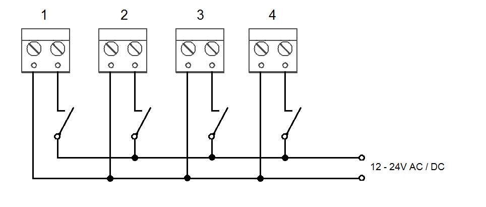 |
Example of Input Circuit Connection
Output Relay Connection
Every I/O Module is equipped with 4 bistable relays with the maximum load of 250 V / 5 A per contact. Never exceed this limit to avoid system damage. When the relay is closed, the respective LED signals this state. You can configure the relay function in the 2N® Service Tool application.
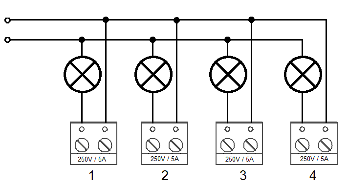 |
Example of Output Relay Connection
Warning
- Never exceed the voltage and current limits specified in the Technical Parameters for the load applied to the relay contacts to avoid system damage.
Warning
- Never connect any important structural devices such as brakes, door locks, security equipment, etc. to the relay outputs. The I/O Module is not designed and must not be used for such installations. Connect only the devices that will not be damaged by unexpected relay contact disconnection (CU remote upgrade, bus restart, etc.) such as unimportant signalling lamps, ventilators, shaft lights, etc.).
- The manufacturer shall not be held liable for damage incurred as a result of improper installations on the relay contact.
Mounting Types
See below for the mounting types and necessary components. Install the device on sites not exposed to water leakage or condensation.
Wall Mounting
Use appropriate wall plugs and screws for mounting (not included in the delivery). Hang the device using the pre-drilled holes on the device bottom.
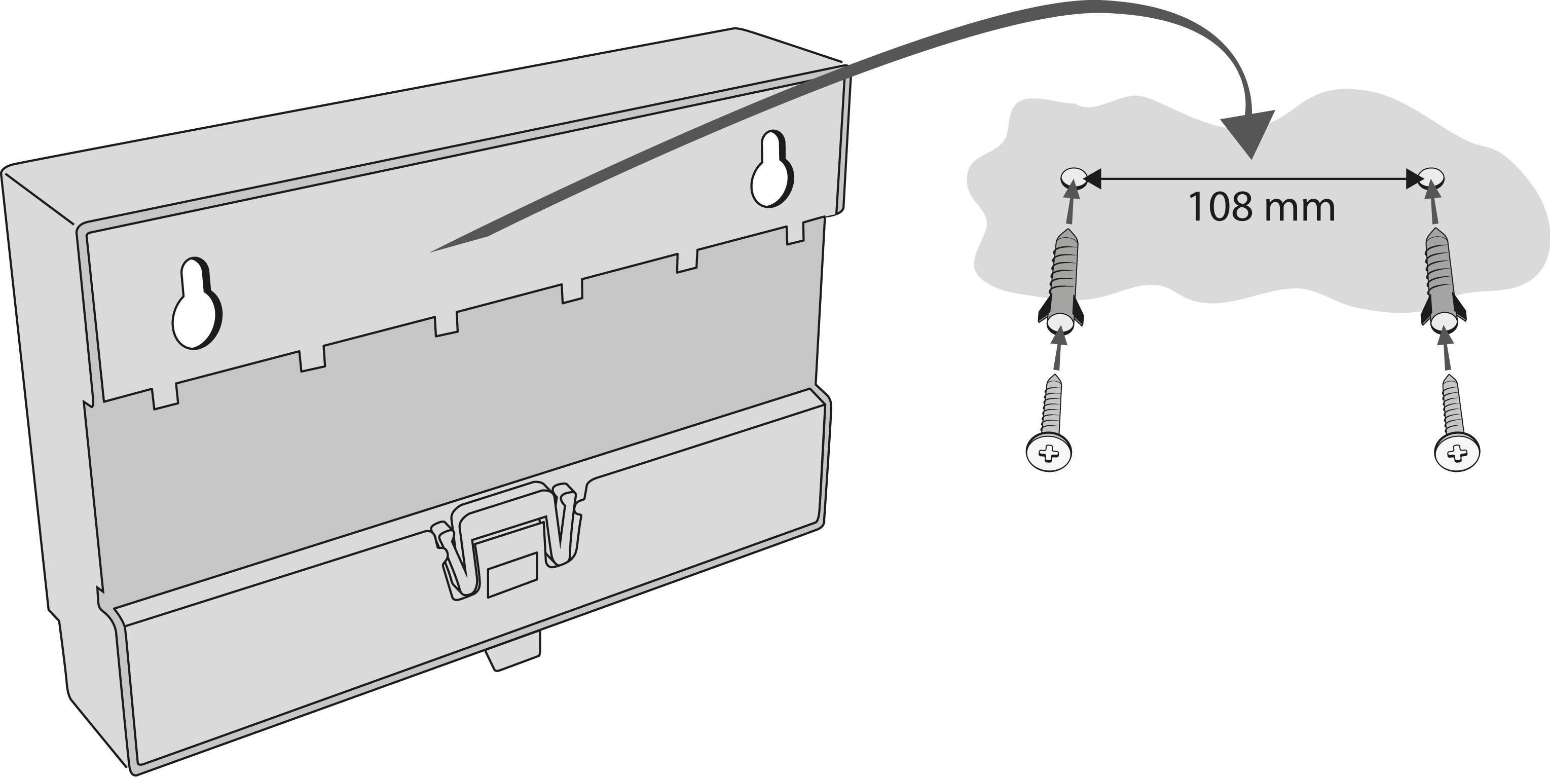 |
Wall Mounting
DIN Rail Mounting
Mount the device on a standard TS 35 DIN rail. The recommended DIN rail length is 14 cm.
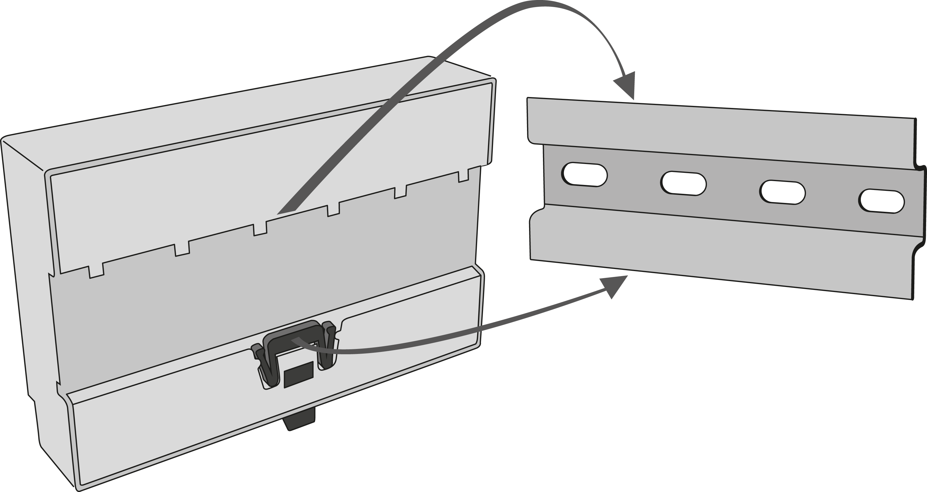 |
DIN Rail Mounting
Caution
- The warranty does not cover any defects or failures of the product arisen as a result of improper mounting in contradiction to these instructions.
- A wrong mounting procedure may lead to damage to the electronics due to water infiltration. The splitter circuits are constantly under voltage and water leakage causes electrochemical reaction. No warranty can be claimed for products damaged in this manner!