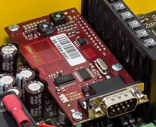
2.14 RS232 Module
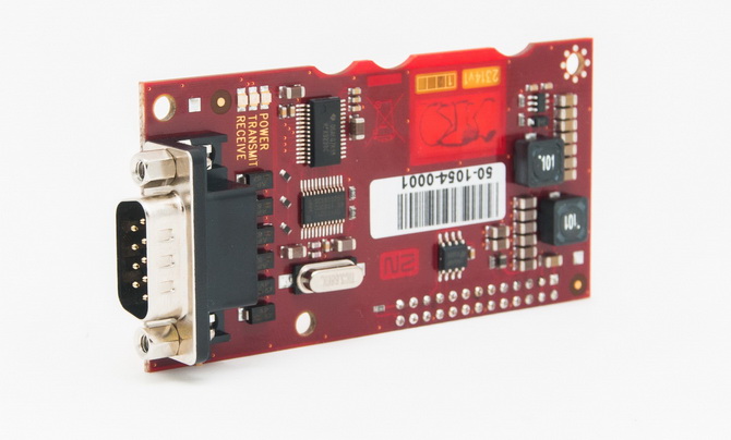
Description
The RS232 module helps you receive AT commands from the lift Central Unit (CU). Some AT commands are supported only. Use the 2N® Service Tool to set the transmission rate (115200 by default).
 |
Before You Start
Product Completeness Check
Check whether the product package is complete before installation.
The RS232 module package contains:
- 1 electronics board (RS232 module)
- 2 long threaded spacers, 1 short screwed spacer
- 1 screw
- RS232 cable
- cable bushing
Description of Connection
- Keep the CU disconnected from the mains.
- Loosen the three screws on the upper cover of the CU.
- Move the CU upper cover in such a way that you can remove it.
- While removing the cover, proceed with caution - be careful about the earth wire connecting the cover with the CU bottom part. Do not disconnect the wire unless there is a reason to do so!
- Disconnect the back-up rechargeable batteries if connected (using the FASTON cable end pieces connecting the rechargeable batteries with the motherboard).
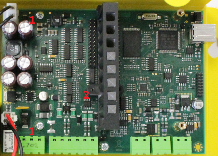
Unscrew 2 screws (1) and replace them with 2 threaded spacers. Fit the screwed spacer (2) into the LED plastic cover (see Fig.).
Tip
To make your spacer mounting easier, turn the screw until it stops and use a cross-point screwdriver to fit the spacer. Having tightened the spacer in the LED plastic cover, use flat-nose pliers to secure the spacer against spinning and remove the screw.
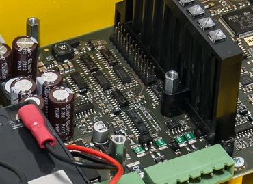
- Now mount the RS232 module. Be careful while putting the module on the pins. Make sure that you have connected all the pins to the module connector.
Having fitted the pins into the connector correctly, you can fix the module using 3 screws (see Fig.).
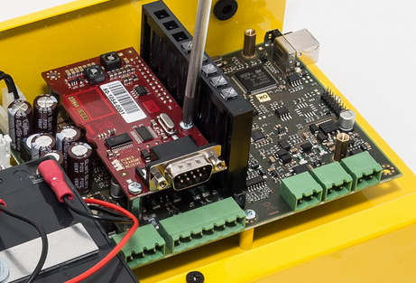
- To mount the RS232 cable, remove the blank module on the CU bottom edge. Put a cable bushing on the RS232 cable and insert it in the empty space (the cable bushing is factory-cut in one point for easier handling).
- Replace the rechargeable batteries and CU cover and tighten the 3 screws to fit the cover.
Supported AT Commands
| AT Command | Example | AT Command Use | Note |
|---|---|---|---|
AT+CMGS= | AT+CMGS="+420603123456",145<CR>sms text<Ctrl+z> or without apostrophes AT+CMGS=+420603123456,145<CR>sms text<Ctrl+z> | Send SMS | <CR> = Enter 145 – international number (including +) 129 – national number |
| AT+CMGF= | AT+CMGF=1 | Select SMS mode | |
| ATE1 | ATE1 | Enable echo | Returns the typed characters to the terminal.
|
| ATE0 | ATE0 | Disable echo | |
| ATE | ATE | See ATE0 | |
| AT | AT | Start command row |
See here for details on AT commands.
Caution
- Use a CU with the GSM/UMTS module for sending SMS.
Serial Port Configuration
You can only set the transmission rate of 9600–115200 bauds for the serial port.
The other parameters are preset:
| Bits per word | 8 bits |
| Parity | no parity |
| Stop bits | 1 stop bit |