5.3 Use
Upon the application launch, you get to the Configuration main menu and then the Parameters – Basic menu, where you can find almost all the 2N® Lift8 Central Unit settings. You are in the offline configuration, which you can modify, save into a file and prepare for download into the CU any time later. The offline mode helps you view the CU settings, logs. You have access to the Configuration and Logs menus. The other menus are meaningful only if the CU is connected. The meaning and description of the parameters and controls are the same as in the online mode (i.e. with the CU connected); see below for details. Follow the CU login instructions in Subs. 5.1. Now let us explain what the menus are used for.
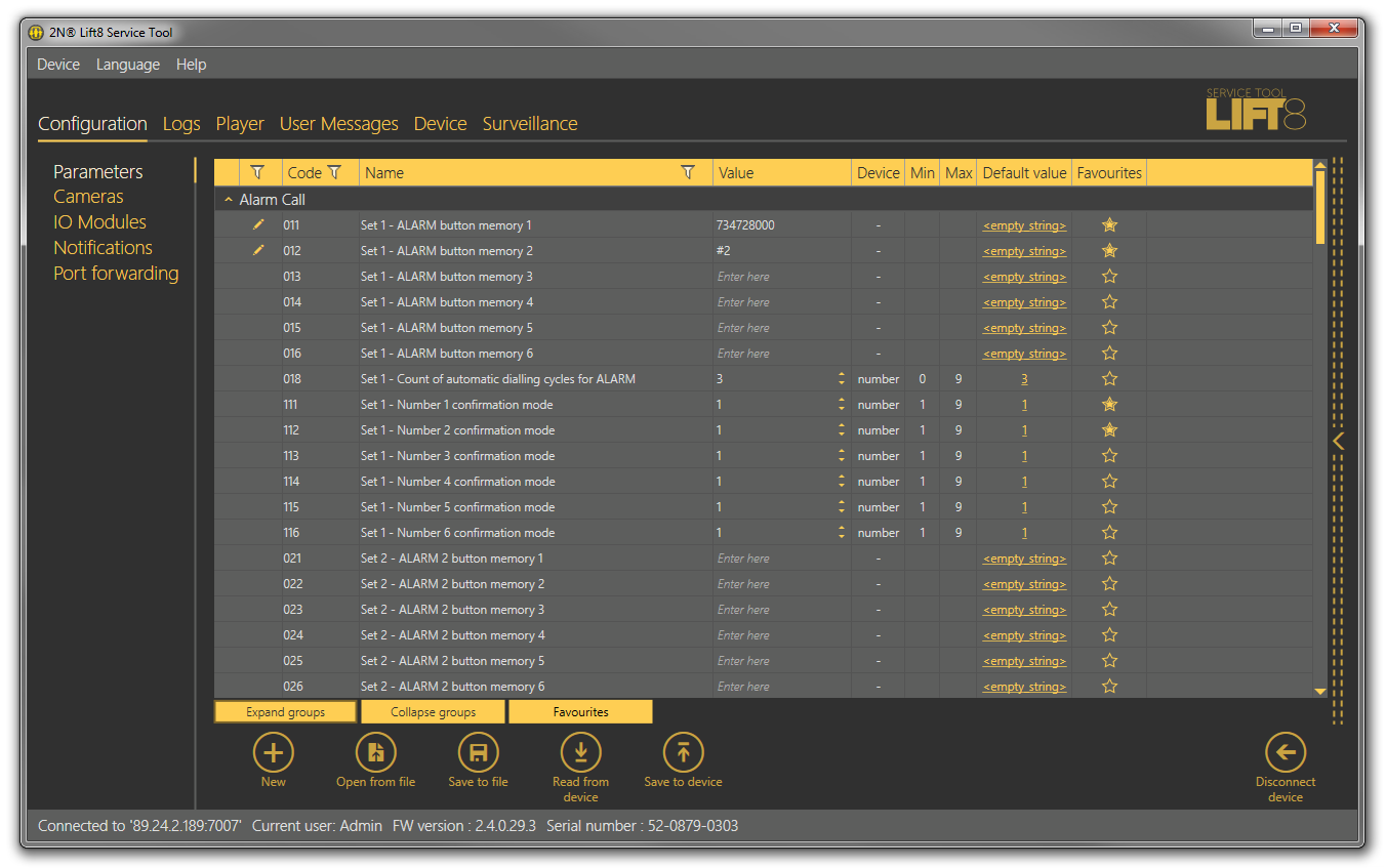
Configuration
Parameters
Having logged in to the CU as described in the preceding subsection, you get into the main configuration menu. The Parameters – Basic menu includes the table of all the 2N® Lift8 parameters including their codes. Refer to Subs. 3.2. for the list of parameters and their meanings. All the parameters are arranged in associated groups for convenience. Moreover, each table row is equipped with a hint, which describes the parameter purpose and setting options. The table includes the following items: Code corresponds to the parameter number in the CU voice menu, Name displays the parameter name, Value shows the currently set parameter value and Unit specifies the parameter unit (if no unit is specified in this column, the value is just a number). Maximum and Minimum define the permitted range of the values to be set. Default value displays the factory value of the parameter (which also appears after the factory reset). Click this value to add it to the value column.
 |
Parameters – Basic Menu
The menu also includes the Expand groups/Collapse group buttons for you to expand the sections and display all the required parameters quickly. Click the Favorites next to the Collapse group button to display your favourite items in the table. Click on the empty star symbol behind a parameter in the Favorites column to select a new favourite item. Similarly, c lick on a filled-in star symbol to unselect a favourite item. Use the Expand groups/Collapse groups buttons also for displaying your favourite items and filtering. A yellow-to-orange colour change of the Favorites button means that the favourite items are only active. Push Open from file to read the back-up data. The Read from device button helps you read the current set of parameters from the CU. Having completed the settings, click Save to device to save the changes into the CU memory. Filtration is a convenient searching tool. Set the filter for each column separately and combine the filters to find the required data as quickly as possible. Click the funnel symbol in the selected column to activate the filter. Activation is indicated by a colour change of the funnel symbol; see the figure below.
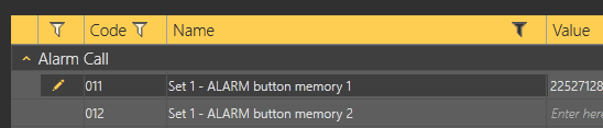 |
Left – Inactive Filter, Right – Active Filter
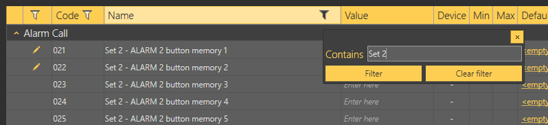
Each column with the funnel symbol includes filter settings; see the figure below. The Contains function finds the searched string in all the column items and returns all the occurrences. Enter a text into the string field and click Filter to activate the filter and find all the searched items in the column. Use another filter to make your search more precise and efficient. Having completed filtering, click Delete filter in the used columns to delete all the active filters. If you did not delete the setting, the filtration settings would keep active even upon the CU logout and you would obtain filtration results instead of complete information in your next search.
Tip
- You can also delete the active filters using a context menu displayed by clicking the right mouse button anywhere in the table or pressing the Alt+R hot key.
 |
Filtration Setting Result
The pencil symbol is displayed whenever a default parameter is changed to highlight the parameters that have been changed in the configuration.
Tip
- Each table row is equipped with a hint including parameter description for convenience.
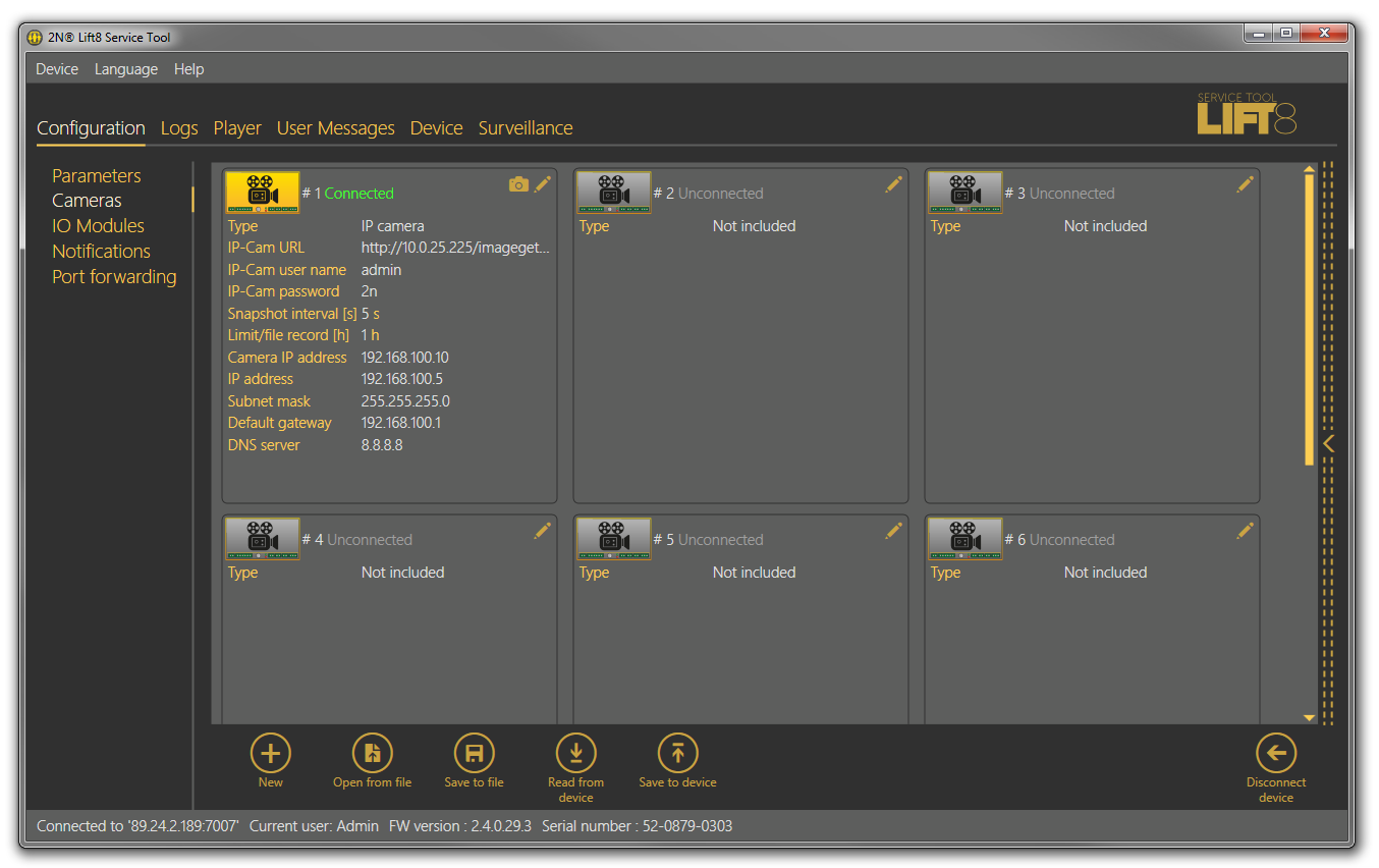
Cameras
Switch to the Cameras menu to configure the camera modules. There are 8 frames in the window, one for each camera module on the given address. Each frame includes a camera module icon, which symbolises the module state, plus the module number and state description. A grey icon and greyish 'Not connected' description indicate an unconnected camera module. A yellow-highlighted icon plus a green 'Connected' text indicate that the camera module is connected to the CU and the camera is online. See the figure below.
 |
Cameras Menu
The two buttons in the right-hand upper corner of the frame are active when the camera module is online. The pencil icon (Edit) is active even if the camera module is disconnected. Use Edit to switch to the camera module configuration menu. The camera icon helps you get the current image from the camera. Click camera editing to open a new window - Camera configuration. The window can be different for different cameras as those parameters are only displayed that are valid for the given camera type. For example: with an IP camera the image web link is specified instead of image parameters. Make sure that the resolution and compression parameters are set in the camera before connecting the camera to the camera module. Now let us describe all the parameters to be configured. Type selects one of the three available camera types: IP camera, RS 232 and RS 485. None is selected by default. Having selected the camera type, you can define the other parameters: Resolution, which defines the image size to be sent by the camera: 640 x 480, 320 x 240 and 160 x 80, Compression (only for RS232), which defines how to compress an image from the original bitmap to the .JPEG format, and IP camera URL, which defines the image path to be entered into the browser. IP-Cam username is IP camera access user name (login). IP-Cam password is IP camera access password. The DHCP server in the camera module ensures that the connected camera should always get the same address (10.0.0.1). Add the image address in the device as shown in the figure below. Enter a value in seconds in the Snapshot interval to define the image loading interval in case the camera saves its images on a memory card. Define the maximum size of the .mjpg file in hours in the Record limit/file parameter for memory card saving. The IP camera configuration section also includes DHCP settings and camera module IP configuration. Refer to Subs. 2.12. for more setting and function details.
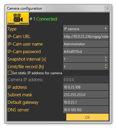 |
IP Camera Configuration
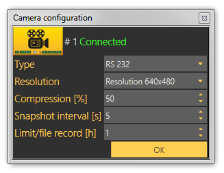 |
RS232 Camera Configuration
Press OK to confirm the settings and add the values to the table. Click Save to device to store the data in the memory and use it in the CU.
Caution
- Caution! Whenever you click Save to device, the whole configuration table will be overwritten. Make sure that you have loaded the valid parameters to avoid data loss.
Click the Camera button to open a camera preview. Three controls are available in this window. Click Get new image to start loading an image from the camera module. Image loading via a 2-wire bus is a rather time-consuming process depending on the image size: transmission of a serial camera image of the resolution of 640 x 480 and with the minimum compression takes a few tens of seconds. The other two buttons help turn the image left or right to optimise the view if the camera scans under the angle of 90°, for example. Close the window to quit the preview.
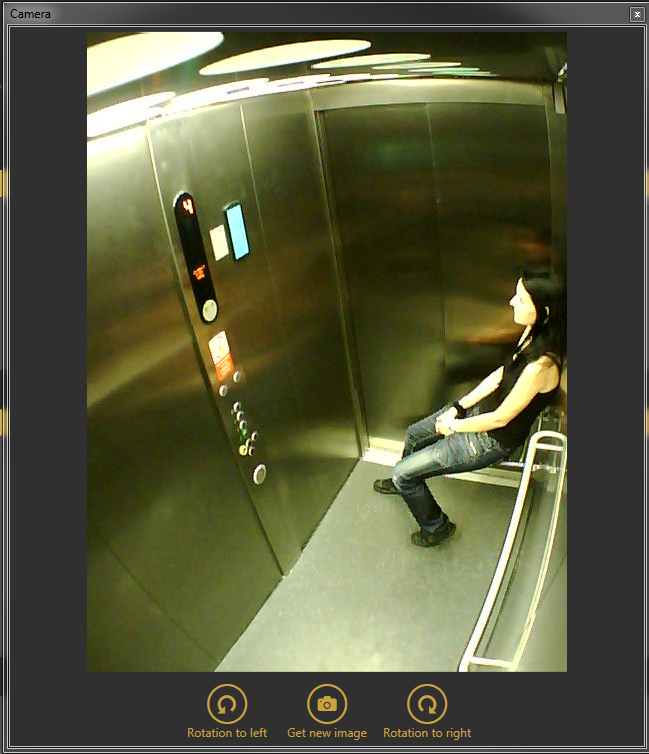 |
Camera Window
IO Modules - Basic
Open the IO Modules menu to configure the IO modules. There are 8 frames in the window, one for each IO module on the given address. Each frame includes an IO module icon, which symbolises the module state, plus the module number and state description. A grey icon and greyish 'Not connected' description indicate an unconnected IO module. A yellow-highlighted icon plus a green 'Connected' text indicate that the IO module is connected to the CU and the camera is online. See the figure below.
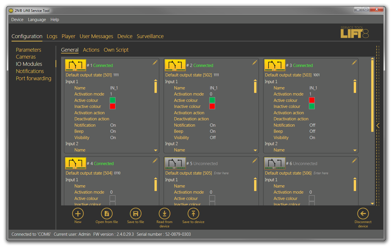 |
IO Modules – Basic Menu
The pencil icon (Edit) in the right-hand upper corner of the frame is active even if the camera module is disconnected. Click Edit to open a new window – IO module configuration. Like in the overview, the IO module state is displayed in the upper part of the window. The IO module input states are displayed below the IO module state.
Name is the first parameter in the window. Select a brief name for the input sensor characterising its type and location: Smoke sensor on shaft ceiling, for example. Activation mode is a negation of the input circuit: if you set 1, the input is active if logic 1 is set on it, and if you set 0, the input is active at logic 0. Activation/Deactivation colour defines the colour of an active/inactive input to be displayed next to the input in the Surveillance menu. Activation action specifies the action to be executed whenever the input becomes active and Deactivation action defines the action after the input passes into the inactive state. See the Action menu below for how to set the actions. Set the outputs similarly: enter the function name (Ventilator 4, e.g.), set the output relay negation in the Activation mode and specify the output colours for the Surveillance menu.
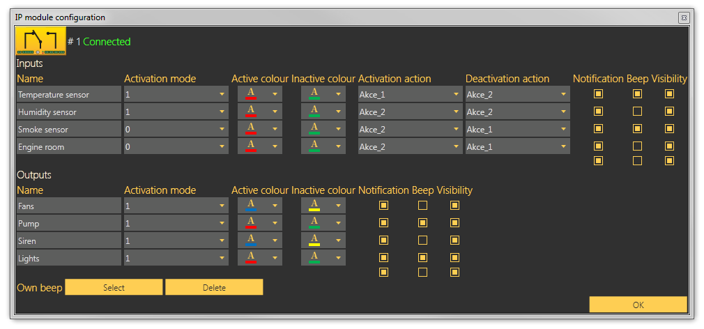 |
IO Module Configuration Window
Select/unselect the checkboxes to the right to enable/disable display of relevant information. Select Display inputs to display information on all the IO module inputs. Check off Display outputs to display the outputs. Select Notification to enable/disable the notification pop-up window. Tick Beep to enable sending of the dialtone to your system output (speakers/headset) whenever a new notification message arrives. Find Custom beep in the left-hand bottom corner. Click Select to select an audio file from your disk to be played as notification, or press Remove to remove the user file and start using the default sound again.
IO Modules - Actions
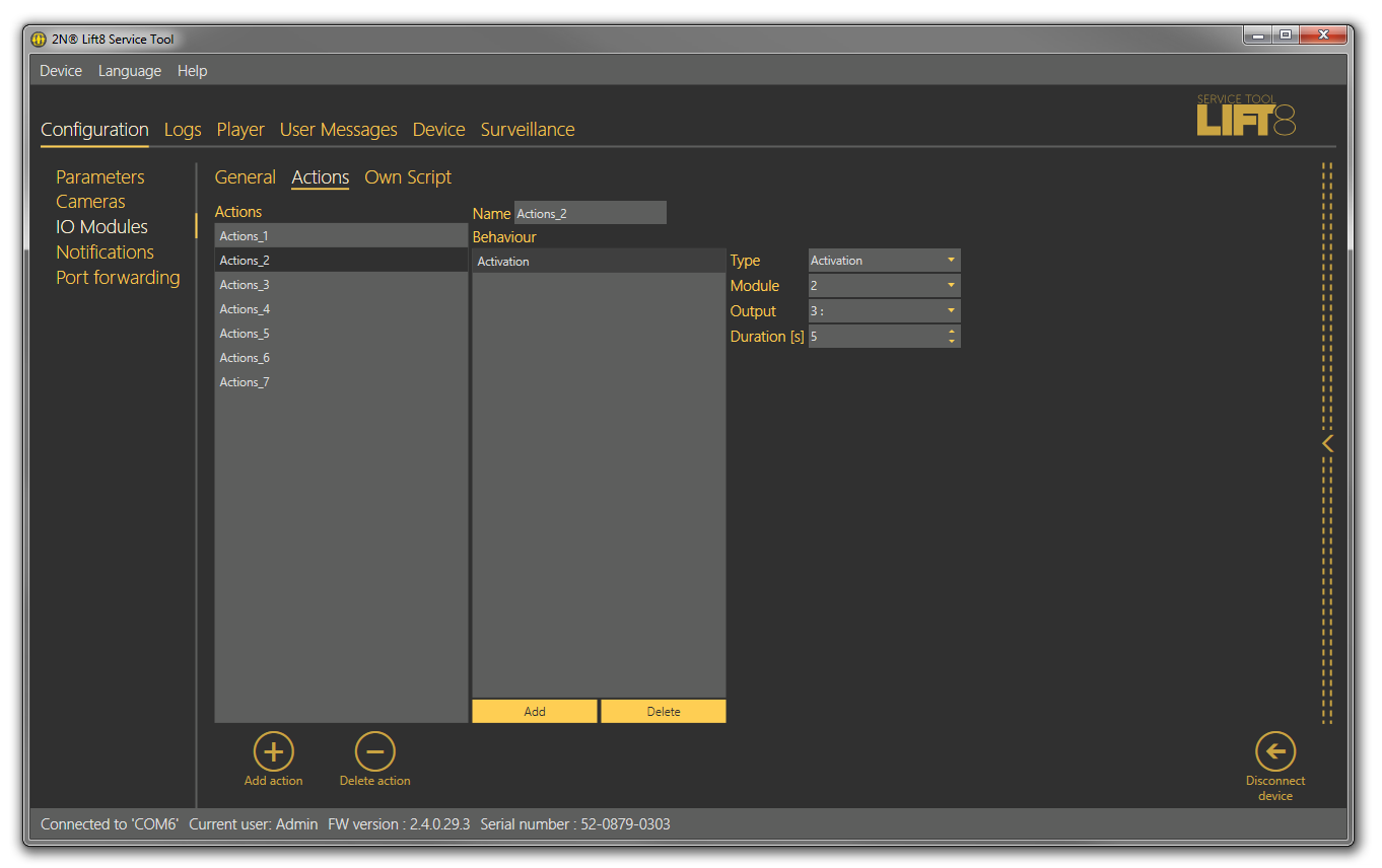
The Actions menu helps you set the actions/commands to be executed. These actions are initiated by changes on the IO module inputs and set as shown above. Click Add action to create a new action. In the settings to the right rename the new action, specify a list of tasks (Behaviour) to be performed: Activation, Deactivation, Send SMS and Rescue end. Activation activates the relay contacts. Select more parameters in the extended settings to the right: module number on which the relay state change occurs, output number including description for better orientation and task duration. Deactivation deactivates the relay and is configured similarly. The only difference is Send SMS, where you enter a phone number and SMS text of the maximum length of 160 or 70 characters depending on the encoding type. Use GSM 03.38 or UCS 2 for diacritics and non-standard character sets. One SMS is sent at a time. Long, multipart SMS are not supported. Rescue end helps you select the shaft(s) for which the rescue mode shall be terminated. With this option you terminate the rescue mode in all the selected shafts. Click Load configuration to save the actions to the device on the Basic tab.
Tip
- If you keep the default value 0 in the Duration parameter, the relay will keep closed/open during the input activation time.
- Example: if input 1 keeps 10 s at logic 1, the associated relay 1 will keep closed for 10 s too.
 |
IO Modules - Actions Menu
IO Modules – Own Script
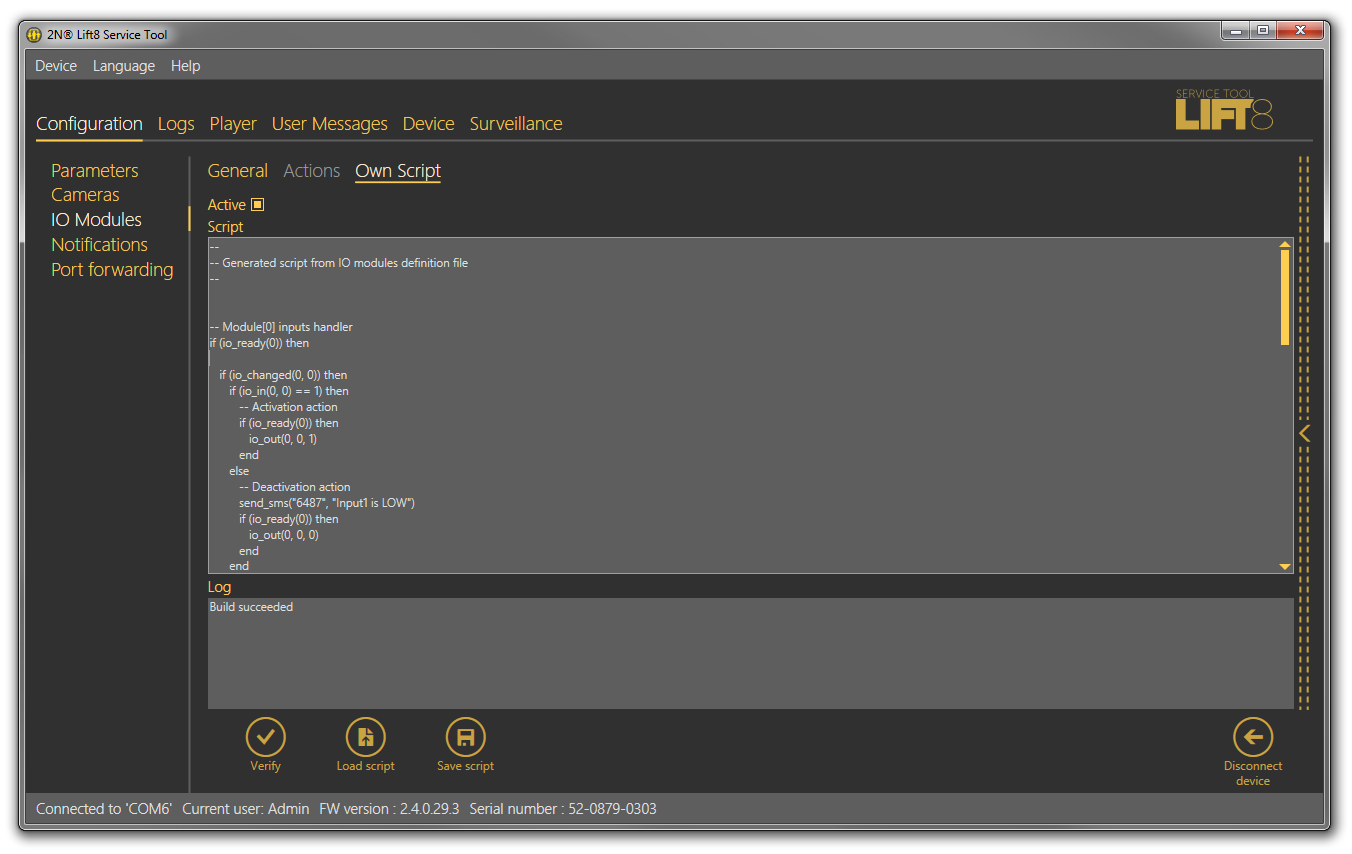
The Own Script menu enables advanced users to edit scripts with own installation logic instead of using graphical action settings. This solution is useful for installations where identical parameters are defined and can be simply copied to multiple central units. The LUA open-source programming language is used for the script. Refer to www.lua.org for more details.
 |
IO Modules – Own Script Menu
To edit a script of your own, first select the Active checkbox to disable the current graphical parameters and enable your own script settings. Programming should be made by a duly trained person. Refer to faq.2n.com for examples. Having completed editing, click Verify to check the code entered. Click Save script to save the properly verified code onto your PC disk. Click Load script to load a file from the disk and add it to the script editing field. Click Load configuration on the Basic tab to save the completed script to the device. The functions below are available.
| Functions | Description | Parameters |
|---|---|---|
| io_out(m,a,s) | Set module output state | m=module_pos a=output_addr s=output_state |
| io_in(m,i) | Get module input state | m=module_pos i=input_addr return input state |
| io_changed(m,i) | Checking module input was changed | m=module_pos i=input_addr return true if input changed |
| io_ready(m) | Checking module is ready | m=module_pos |
| send_sms(p,s) | Send SMS | p=phone_num s=sms text |
| rescue_end(<shaft_list>) | Rescue mode end | shaft_list=shaft numbers separated with a comma The rescue mode is terminated in the shafts where no alarm call is active. |
| io_out_get(m,a) | Output value | m=module_pos a=output_addr |
Events
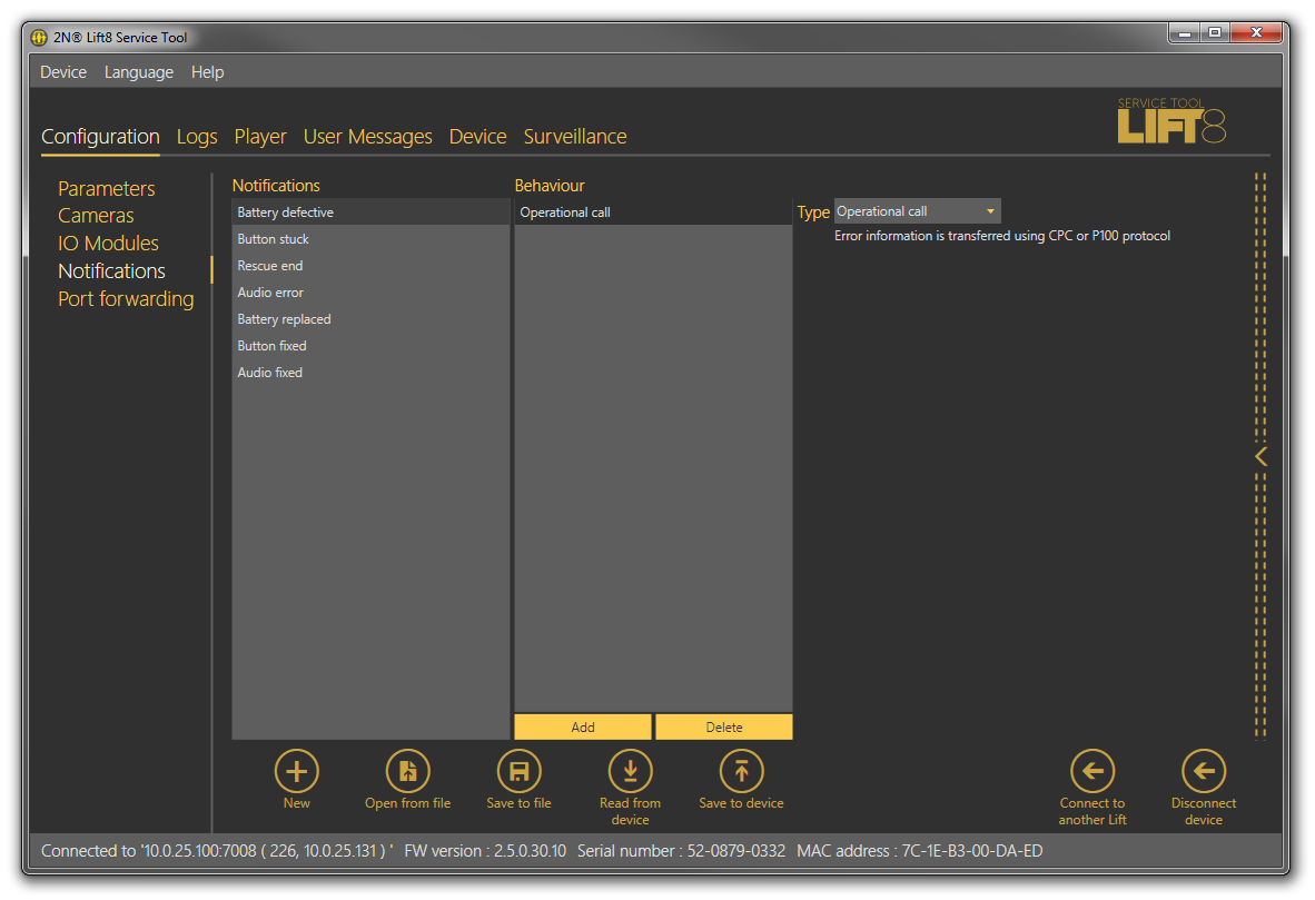
The Events menu helps you configure how the CU shall behave when an event is detected. The events are mostly pre-defined system events and you just choose the type of response to them. Four events are defined at present.
- Replace battery – the event is activated automatically when the set battery life expires or the battery capacity is too low. Refer to Subs. 4.11 for more details.
- Button stuck – use parameter 969 (ALARM button test) for configuration. Refer to Subs. 4.9 for more details.
- Rescue end – the event is executed when the rescue process has been completed. Refer to Subs. 4.10 for more details.
- Audio error – the event is activated when the audio test fails for three times. Refer to Subs. 4.8 for more details.
- Battery replaced – OK state to Battery replace.
- Button fixed – OK state to Button stuck.
- Audio fixed – OK state to Audio error.
 |
Events Menu
When an event is detected, you can specify a list of tasks to be performed: Activation, Deactivation, Send SMS, Send system SMS and Error call. Activation activates the relay contacts. Select more parameters in the extended settings to the right: module number on which the relay state change occurs, output number including description for better orientation and task duration. When set to zero, the output state change is permanent. Deactivation deactivates the relay and is configured similarly. The only difference is Send SMS, where you enter a phone number and SMS text of the maximum length of 160 or 70 characters depending on the encoding type. Use GSM 03.38 or UCS 2 for diacritics and non-standard character sets. One SMS is sent at a time. Long, multipart SMS are not supported. Send system SMS means that the message text is pre-defined in the system and the only parameter to be completed is the phone number. If you select Error call, the CU shall make a call to the number defined in the error call set: parameters 081–086. The error information is then transmitted via CPC or P100. Click Save to device to save the actions into the device.
Caution
- You can send SMS only if your CU is equipped with a GSM or UMTS module.
- Make sure that communication via CPC or P100 is set correctly in parameters 181 - 186 to make successful error calls.
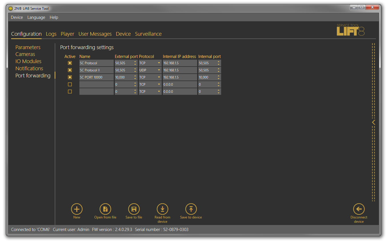
Port Forwarding
Port forwarding helps you get connected to devices located in the LAN. It is because such devices are hidden behind the WAN IP address to the public internet users. This service can only be used via a VoIP or UMTS/GSM module as the PSTN module does not support this type of data transmission. The user gets connected to the external WAN address and a defined port and then is automatically forwarded to the LAN IP address behind the LAN module or another port as defined by the user.
 |
Port Forwarding Menu
You can define up to five ports to be forwarded to selected IP addresses. Specify the following parameters: select Active and then define Name, External port, Protocol (TCP/UDP), Internal address (depending on the LAN module range) and Internal port (LAN port to which communication is to be forwarded).
Caution
- Port forwarding is only available if a VoIP, UMTS or GSM module is mounted in the WAN interface!
- Make sure that a LAN module is mounted to make this service work!
- Never forward Lift8 system ports used for communication, namely:
- 7007 – Service Tool communication port
- 7008 – Lift8 Server default communication port. To change this port, refer to parameter 1232.
- 5060 – SIP PROXY default communication port. To change this port, refer to parameter 1109.
Logs
The Logs section helps you view the diagnostic reports included in the log files. No logs are displayed upon the application launch. Download the current logs from a file or the CU upon login.
Logs – Basic
The Logs – Basic menu includes a table with necessary data. Use the checkboxes below the table to select the table columns. Select the parameters to display the required information: display/hide the timestamp, log level and log group. Click Auto refresh to enable automatic screen update in selected time intervals. Press Read from device to read the current logs from the CU connected. The following items are displayed in the table: Timestamp, which defines the date/time in which the event was captured, and Level and Source, which define the log type and source respectively. Message includes the information itself. The State parameter above the table specifies how many logs (rows) have been read and the log start/end time.
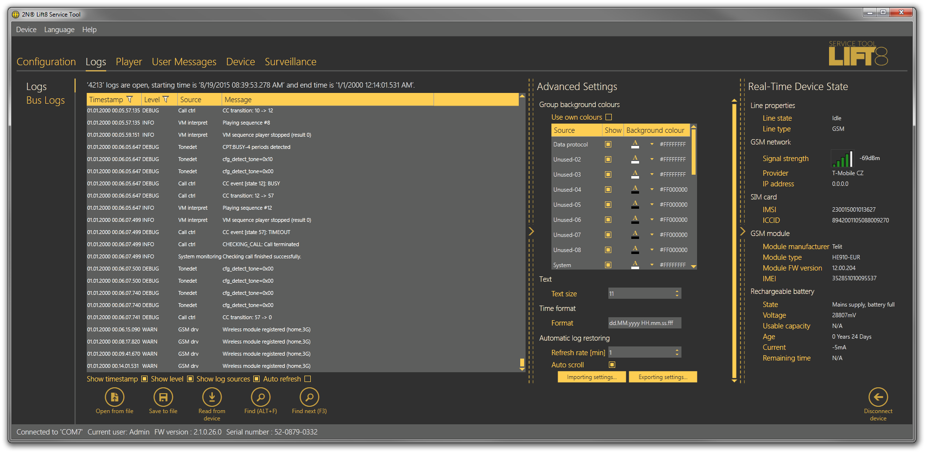 |
Logs Menu
Save the captured log for later analysis in the left-hand bottom part. Click Find to find a message in the log. Enter the string to be searched in the dialogue window. Click Filter to find the first occurrence and Find next to find the next occurrence. Use Advanced settings to enable/disable message types and assign colours for easier log displaying and other advanced options. See below for details.
Tip
- The logs should only be analysed by duly trained persons or your Technical Support department.
Log Finding
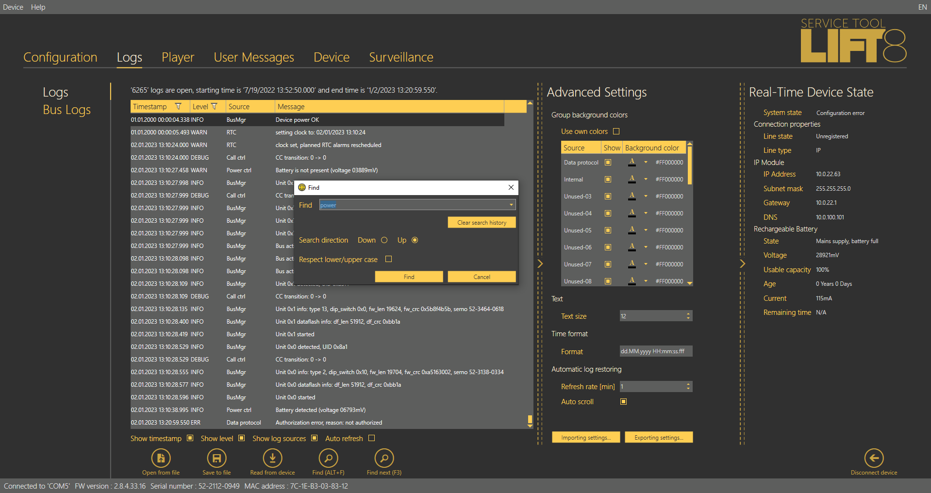
Find Function
Use the Alt + F combination to find the logs in 2N® Lift8 Service Tool. In the Find browser, you can also use the Delete history function to delete all strings left in the Find field. Use Upper/Lower case for search facilitation if necessary.
Logs – Advanced Settings
Logs – Advanced settings is displayed to the right in a hideable form. The Group background colours table helps you set specific background colours for the selected messages. Select the Use specific colours checkbox to activate the user background colour settings for the log groups located below. The change will occur immediately after check-off. Text helps you modify the text size. Moreover, you can configure the Time format: either use the system date/time format or define a format of your own (dd.MM.yyyy HH.mm.ss.fff). Not all values have to be completed, you can also arrange them as you wish respecting the general Custom Date and Time Format Strings rules (see here for details, e.g.). Auto refresh logs is the last option. Set the Refresh rate in minutes a tick off Autoscroll to display the latest log row all the time.
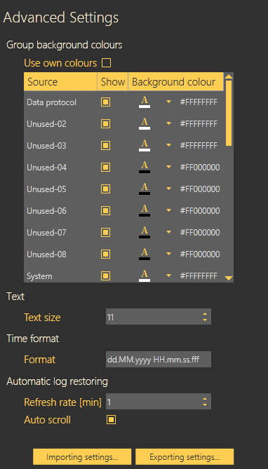 |
Advanced Settings Menu
Save configuration and Upload configuration help you save and load your advanced settings respectively onto your PC disk for later use.
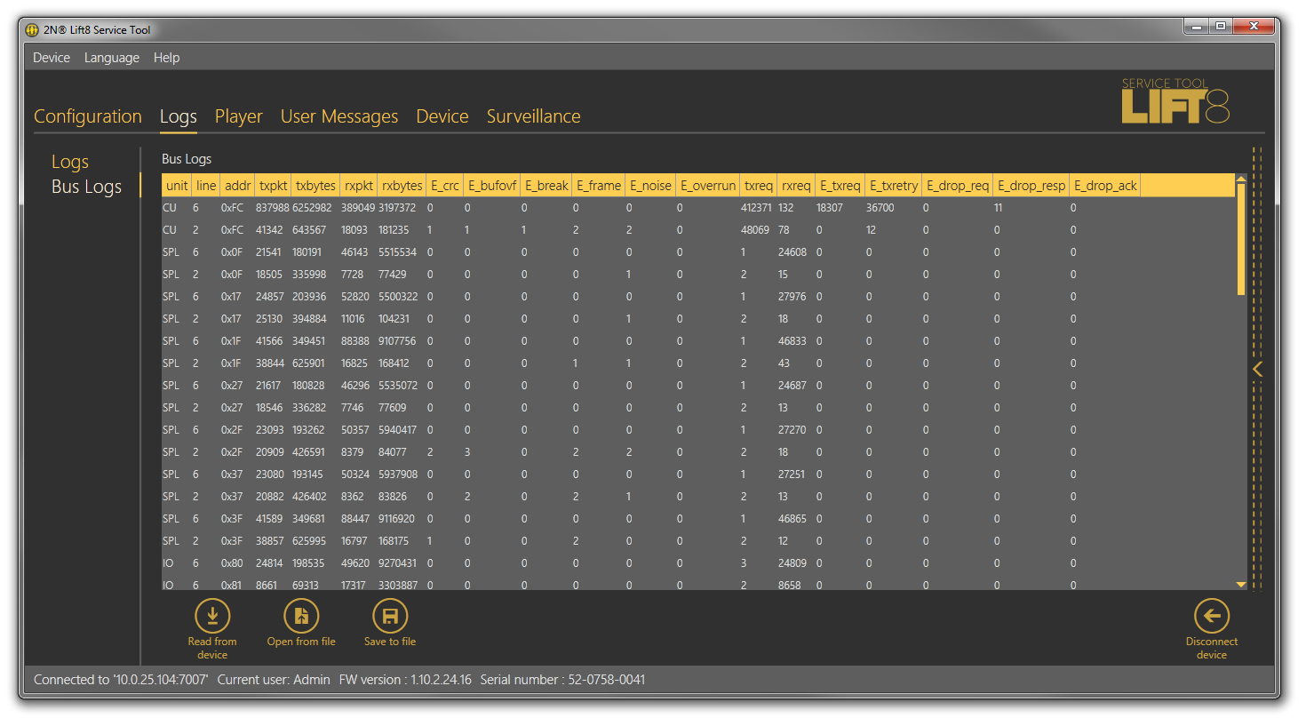
Bus Logs
This menu has been introduced specifically for monitoring all communication along the bus between the bus-connected devices and the Central Unit. Each row symbolises one device connected. The table columns specify the device, bus, address (for later search in the Logs menu) and communication parameters.
 |
Bus Logs
Click Save to a file to save a log for later use. Click Open from a file to open the statistical data offline. See the table below for the columns.
| unit | Unit name (CU = Central Unit, AU = audio unit, SPL = splitter, CAM = camera module, IO = I/O module) |
|---|---|
| line | Line type (6 = 6-wire, 2 = 2-wire) |
| addr | Unit address |
| txpkt | Count of packets sent |
| txbytes | Count of bytes sent |
| rxpkt | Count of packets received |
| rxbytes | Count of bytes received |
| E_crc | Count of CRC errors |
| E_bufovf | Count of UART errors – buffer overflow |
| E_break | Count of UART errors – incorrectly received break |
| E_frame | Count of UART errors – incorrectly received frame |
| E_noise | Count of UART errors – incorrectly received bit |
| E_overrun | Count of UART errors – received byte overwritten with a new value |
| txreq | Count of requests sent |
| rxreq | Count of requests received |
| E_txreq | Count of incorrectly sent requests |
| E_txretry | Count of incorrectly received requests |
| E_drop_req | Count of discarded requests (duplicate requests) |
| E_drop_resp | Count of discarded replies (duplicate replies) |
| E_drop_ack | Count of discarded reply confirmations (duplicate confirmations) |
Player
The Player menu helps save records of the cameras connected to the 2N® Lift8 camera modules onto SD cards inserted in the camera modules. You have three options how to play a video record. The simplest is to remove the SD card from the camera module respecting the SD card connection/disconnection rules described in Subs. 2.12., connect the SD card to your PC and copy the data to a local disk directory.
Note
- Or, start the video from the SD card without copying provided you use a high-quality card with a high transmission rate.
- Or, download the video file from the camera module web interface in case your camera module is connected to the LAN.
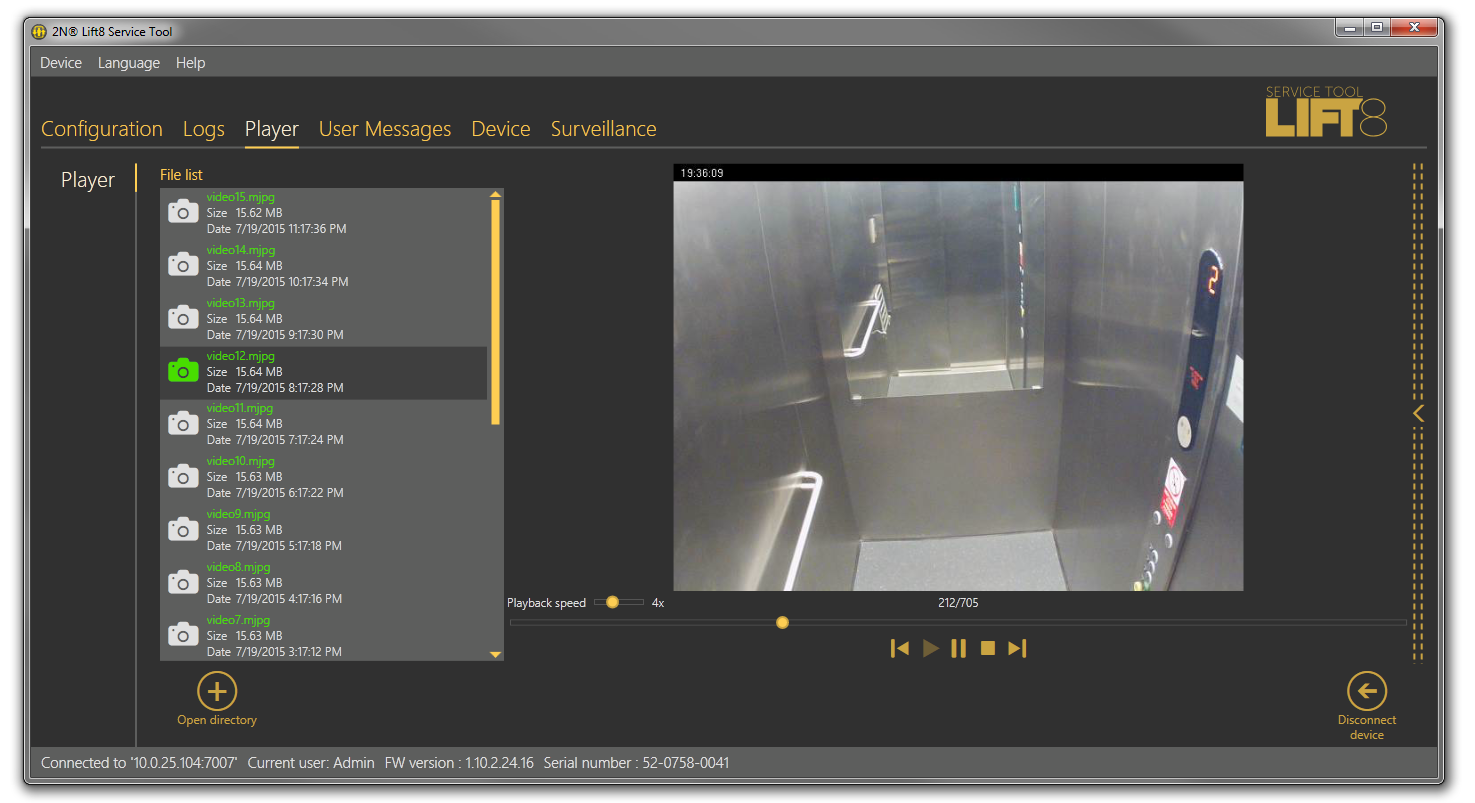 |
Player Menu
Having loaded the files onto your PC disk, click Open directory. Find the proper file directory in the list and select Open to load the video files from the directory into the file list including the file name, size and record date and time. To play a video, select the file in the file list to activate the player to the right. A standard set of video controls is available here. Use the scroll bar or set the playing rate to view the video more quickly (1 to 10 times). Find the count of images in the file and the currently displayed picture in the menu.
Caution
- The player only supports .mjpg files recorded by a camera module. No other formats can be played.
User Messages
User Messages helps you replace the default system announcements with user messages. Load these messages from a file or, in the correct format, via the 2N® Lift8 Service Tool. Use the microphone connected to your PC to record the messages.
Messages
The Messages menu includes a list of user message, which can be replaced with own records. Having entered the menu, you will find no item. Choose one of the following three methods how to fill in the menu: click New set to display an empty list and fill in your own messages, press From device to download the current set of messages used in the CU, or push Load from directory to load a message set saved on your PC. Select the folder with the message set and confirm your selection to load the selected set into the application.
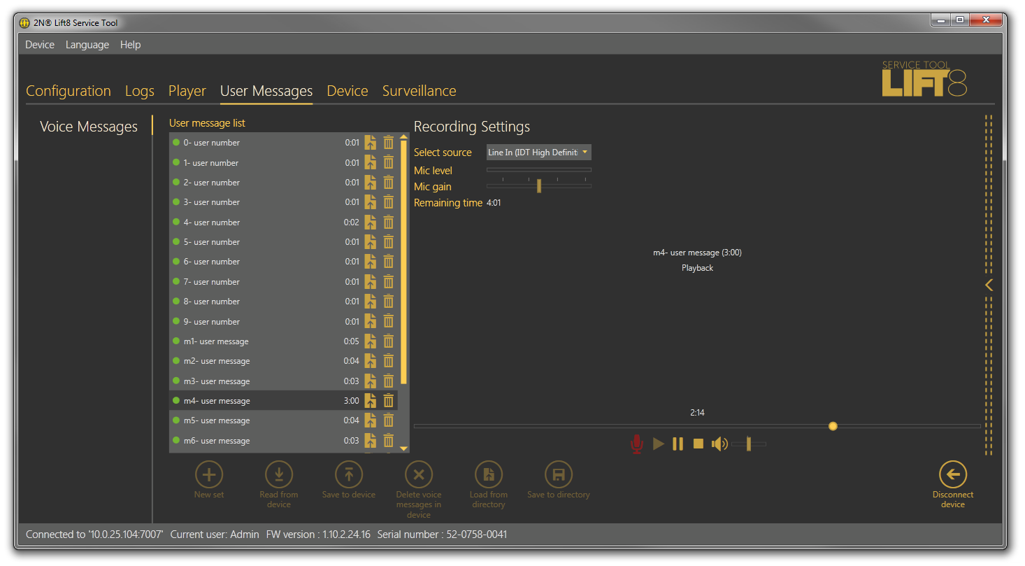 |
User Messages – Messages Menu
The message list includes the message duration and two action buttons: Import message from file and Delete. If a message is not recorded, its total time is 0:00. The total time is displayed for each message recorded. Click on the import button to open a file viewer on the disk to replace the selected message with a new, properly formatted one. If you just select a message, a message player will become accessible to the right for you to play the message. Standard player functions are available too. Press Play to play the message. To record new messages, select the input source. When the microphone icon shines red, start recording a new message, thus deleting the old one.
Note
- The correct format for a message to be added is .WAV. No other files can be recorded.
- A message cannot be recorded until the input device is selected in the recording settings.
The menu is faded during message recording. The player displays the name, total time and current state of the selected message, thus signalling active recording, playing or recording stop. Click the 'Stop" icon to stop recording, Click 'Play' to check the recorded or imported messages. If the message volume level is too low, adjust the input device volume. If the volume is still very low, try to record the message using another device. Having completed message editing, click To device to load the message set into the CU connected. Click Save to directory to save the current set onto your PC disk. Select a message and click the Trash icon to delete the message.
Caution
- The output volume value in the application does not affect the master volume of the record to be saved into the CU. Thus, if the recorded volume is too low, record the message once again and louder.
Tip
- Use high-quality microphones and properly noise-insulated rooms with good acoustic properties for recording to avoid noise and interference in your records.
Recording Settings
Find the Recording settings to the left. Select one of the available input devices in Select source: integrated or external microphone or line input. Mic level defines the microphone input drive level. Mic gain defines the input gain. The total memory capacity for all the messages to be saved into the CU is 8 minutes. The time left for message editing is displayed in the Time left parameter.
Note
- If the microphone input is overdriven during recording, turn down the mic input gain. If the record is too silent, turn up the mic input.
- In case the application gain setting is not sufficient, use the system controllers or an external amplifier.
- When the maximum message time (8 minutes) is exhausted, no more messages can be added. Thus, optimise the message time to record all of your messages.
Device
The Device menu provides information on the 2N® Lift8 Central Unit connected: basic parameters and text/graphic diagram of available Audio Units and splitters. In addition, you can upgrade the CU here too.
Info
The Info menu provides basic information on the state of the device connected: CU FW version, serial number, voice menu language and time. The Time in device parameter displays the current time read from the CU. This parameter is not read online and has to be updated using the Read from device parameter. Set time in device helps you record a time setting of your own. Click on the calendar to set the date/time in hours manually. This value can be overwritten and different time can be set for a different time zone. Click Confirm to confirm the new setting. Click Save current time from PC to device to synchronise the CU time with your PC time value and load the new setting into the CU automatically.
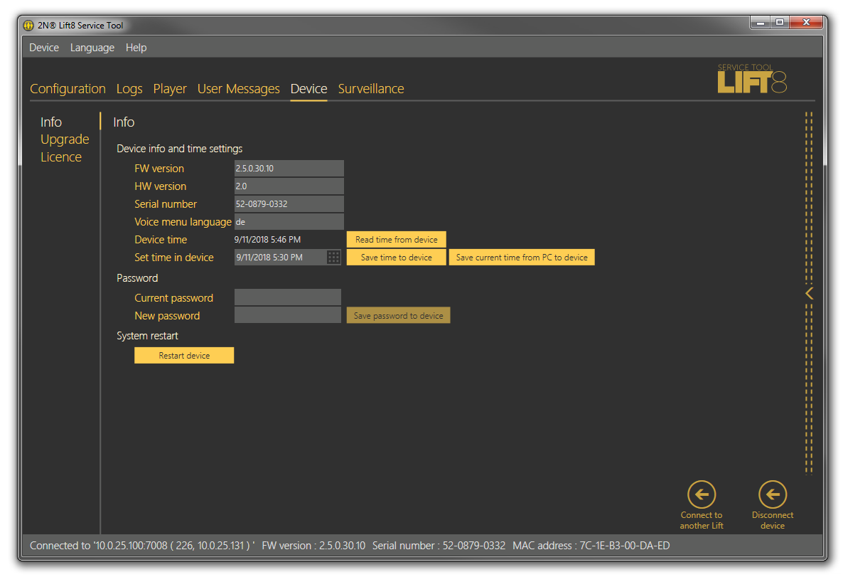 |
Devices – Information Menu
The Password section helps you change the administrator password for the CU connected. Enter the existing password into the Current password and the new password into the New password. Click Save password to device to confirm and save the new setting. Or, click the button to restart the device if necessary and log out automatically.
Note
- Remember to change the password in the 2N® Lift8 Service Tool configuration too for future connections.
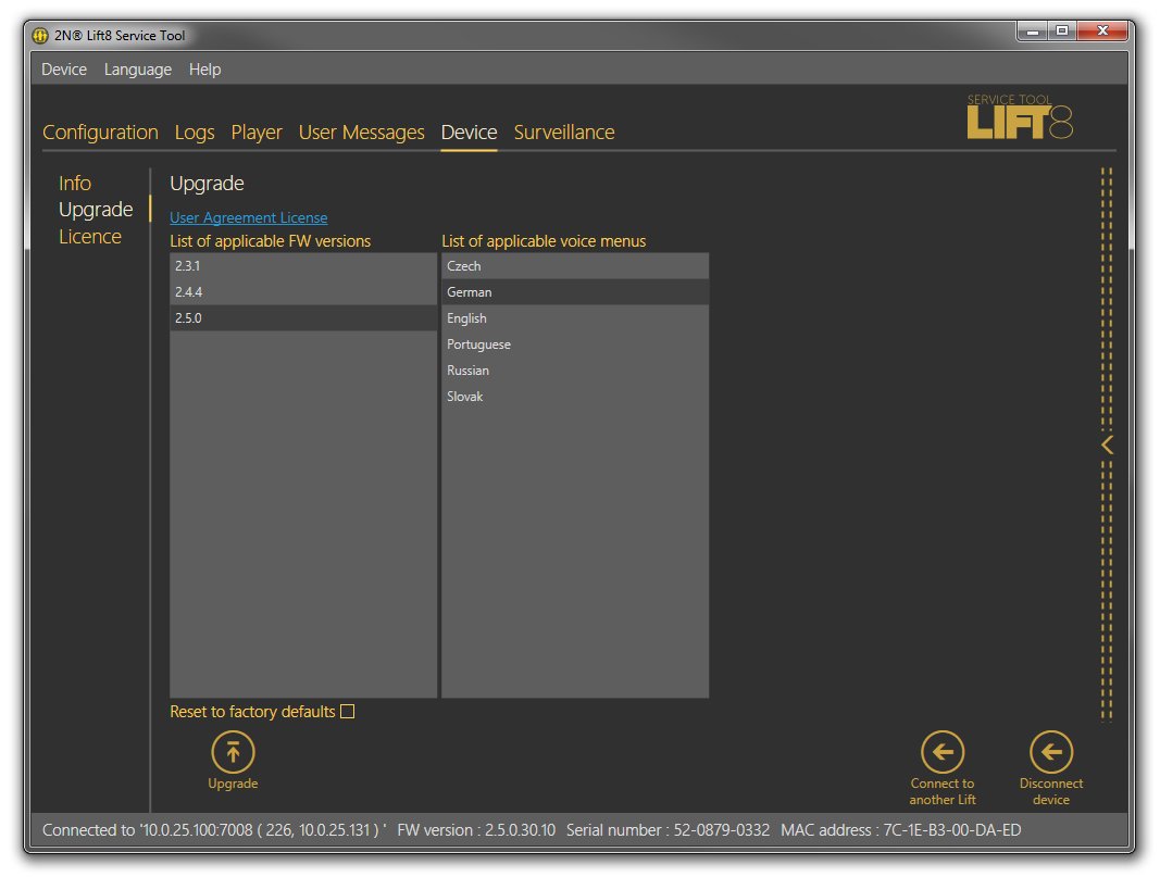
Upgrade
The Upgrade menu helps you upgrade the CU firmware via two menus: List of applicable parameters and List of applicable voice menus. Click on the appropriate name to select the FW version and voice menu type to be loaded to the CU. Having selected the items, click Upgrade to make the 2N® Lift8 Service Tool load the new FW and voice menu into the CU. The menu provides a list of upgrade licences.
Caution
- Having upgraded the FW you will be notified of the CU restart. After confirmation, the restart will be made and the application will be disconnected. Reconnection will not be possible until the system upgrades the Audio Units and restarts. This process may take a few minutes in extensive systems.
 |
Menu Device / Upgrade
Select Reset to factory defaults to delete all user edited changes and restart the audio unit with the factory default values. Select this option and click Upgrade to reset factory default values upon upgrade. This action will only be performed together with new FW, Bootloader or Voice menu loading. To reset the default values only, use the Configuration menu.
Caution
- If you select Reset to factory defaults, parameters 1100 ~ 1110 (VOIP settings) will not be deleted for security reasons.
Licences
The Licences menu is used for adding licence files. The licences to be added to the CU are only applicable in the UMTS/GSM module versions. The licence enables/disables the network (provider) to which the device shall log in. Enter the IMSI code into the licence: particularly the MCC and MNC to define the country and provider permitted for the CU. Enter a greater portion of the IMSI code to specify the SIM cards to be used in one network. You can add up to 10 IMSI codes to the licence. Contact your 2N® Lift8 supplier or the manufacturer's Technical Support department (sales@2n.cz) for the licence file.
Having acquired the licence file, click Open from file and Load to device to open a file browser with the licence location and click Confirm. The program will notify you of the licence change and necessary device restart. Confirm your selection. Re-log in and check the licence. The Allowed IMSI item will display the IMSI codes permitted by the new licence.
Caution
- Any attempt to load licences for another serial number into the CU will be rejected.
- If you fail to log in to a GSM/UMTS network, it is possible that the licence permits a different IMSI range, which does not match the currently inserted SIM card. This state is indicated as follows: the GSM/UMTS module has a sufficiently strong signal, but the EXT. line LED is shining red. Insert the correct SIM card or change the licence file.
- The licence features only apply to the CUs equipped with a GSM/UMTS module.
- There is no limitation as to the other PSTN/VoIP communication interfaces even if the licence is added to the CU.
- If your CU does not include any licence file, its function is not limited and the inserted SIM card can log in to the provider's network, yet with some limitations (roaming, e.g.).
Surveillance
Connected Units
The Connected units menu provides a graphic diagram of all the units connected to 2N® Lift8. The following controls are available: Refresh to update the display, Press HW setting (diagram/text) to print out the diagram/text of all the Audio Units and splitters connected to the given CU. The diagram displays the units like in the application and the text provides the same information as the diagram in the XML format. Click these buttons to export the diagram/text to the printer. Zoom in and Zoom out help you get a closer (more detailed) and more distant view (whole structure) of the diagram/text respectively. The unit watching buttons help you enable/disable the function. The system behaves like with the Reset button. All the units to be watched are green-highlighted and an error is detected and displayed if there is a loss of connection; see the figure below.
 |
Surveillance Menu
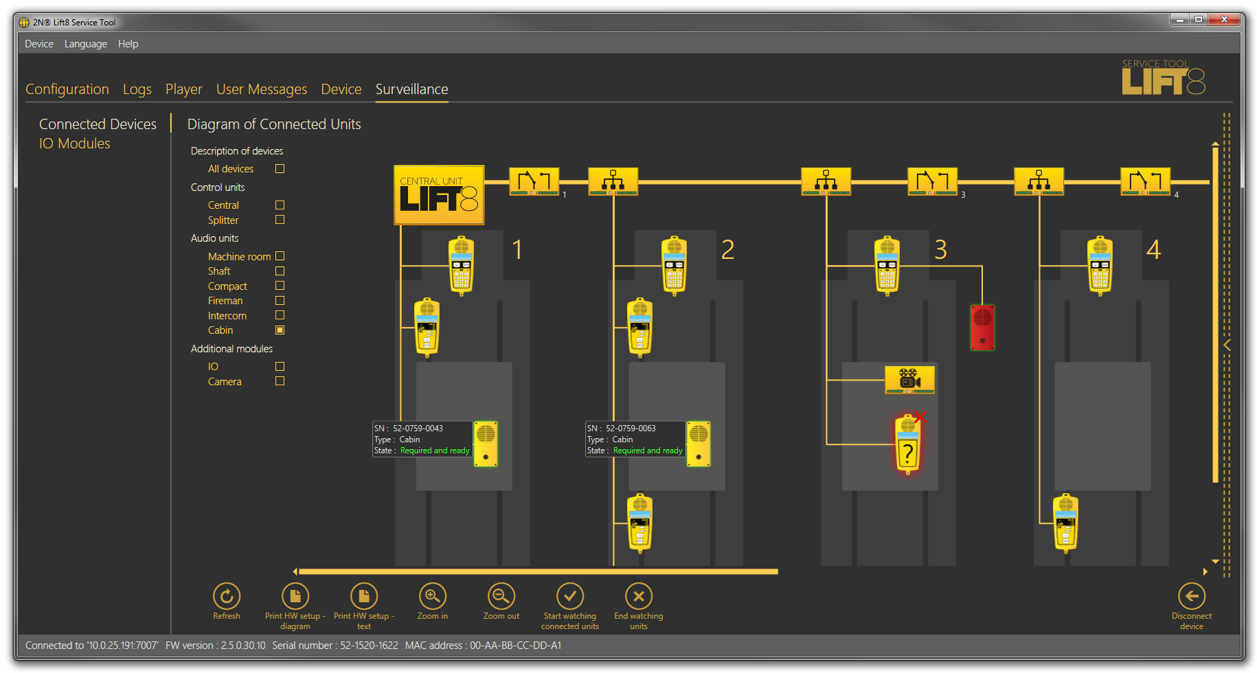
Diagram of Connected Units
The diagram displays graphically all the devices connected to the selected CU: buses, shafts and Audio Units. Tick off the checkboxes in the Unit description to display details on the audio units and select the audio unit type as shown in the figure below. The brief description to the left of the audio unit includes the Audio Unit serial number, type and current state.
If you use the system completeness check, the audio units to be monitored (cabin, Fireman) are marked either green or red. Green means that the audio unit works properly. Red means that the audio unit is in the error state, fails to communicate or is disconnected. Get the audio unit repaired as soon as possible to make your system complete. Or, remove the audio unit from checking in the system completeness check configuration; refer to Subs. 2.1.
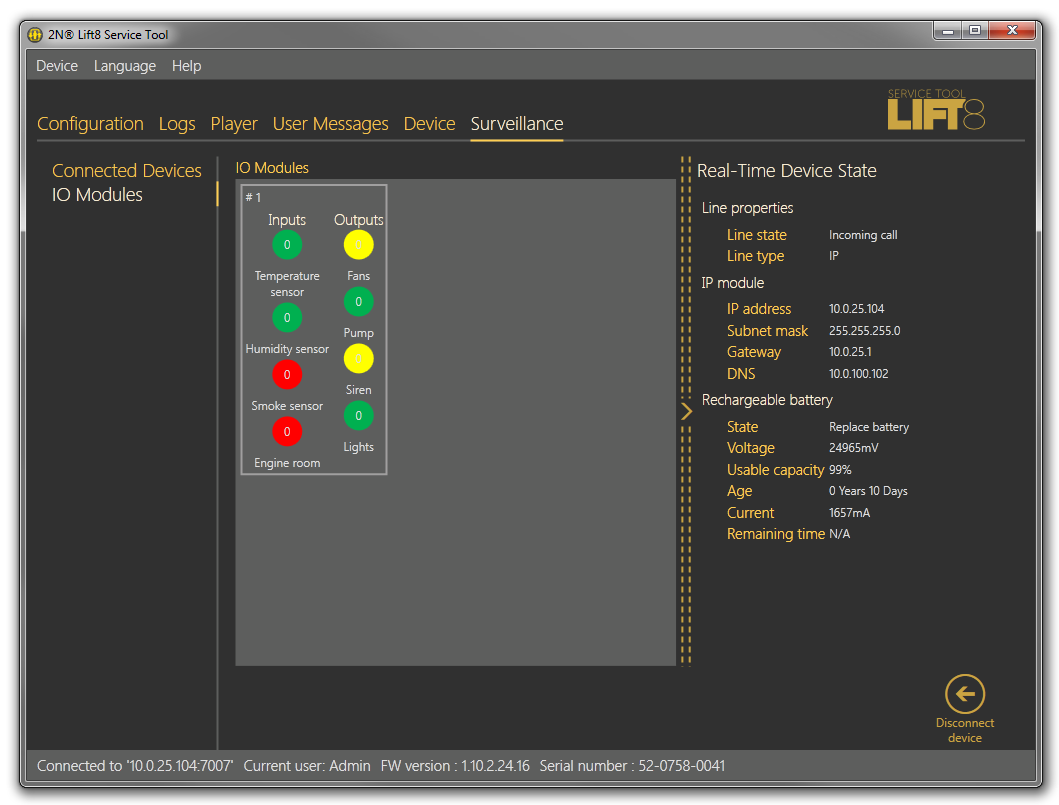
IO Modules
 |
IO Modules Menu
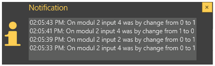
The IO Modules menu helps you monitor the states of the IO modules connected. The IO modules section displays all the modules connected to the bus. Each module is identified with a number, which corresponds to its HW address set on the DPS. Furthermore, states of all the inputs and outputs are included. The inputs and outputs are set to 0 by default upon the system startup. Logic 0 is on the input and the relay is open. Use the settings in the Configuration / IO Modules menu to change the relay position upon startup. A change of the input signal level or setting the relay into the open state will change the signal from 0 to 1 and the user will be notified of the change by a LED colour change and text notification, which provides information on the module, input and signal value that initiated the event. This notification is displayed in a special pop-up window, which is not closed automatically but closing has to be confirmed with a cross. In this way, the user is always duly informed and cannot miss any input change. Disable notification in the Setting / Configuration menu. You can also choose a module to be listed. If you do not enable module displaying in the Configuration menu, the module will not be visible here.
 |
Notification Pop-Up Window
Each IO module is identified with a number and an overview of inputs and outputs. Use the Configuration / IO Modules menu to add a brief description to an input/output. You can also select the active/inactive input/output state colour in the same menu to simplify the visual state identification. The logic state of the given object (input/output) is signalled with digits 0/1 in a colour ring.