2.4.1 2N® Lift8 Machine Room Unit
2N® Lift8 Machine Room (Part No. 918623E) is an audio unit designed for machine room installation for one lift shaft or the Intercom solution. The user does not come into direct contact with this product.
Product Completeness Check
Check the product package for completeness before installation.
The cabin audio unit includes (assembled):
- 1 electronics board,
- 4 terminals,
- 1 mounting panel,
- 1 cover with printing,
- 1 directly or cable connected speaker,
- 1 directly or cable connected microphone,
- 1 declaration of conformity,
- 1 update notification,
- 10 cable ties.
Electric Installation
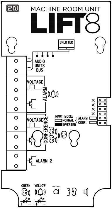
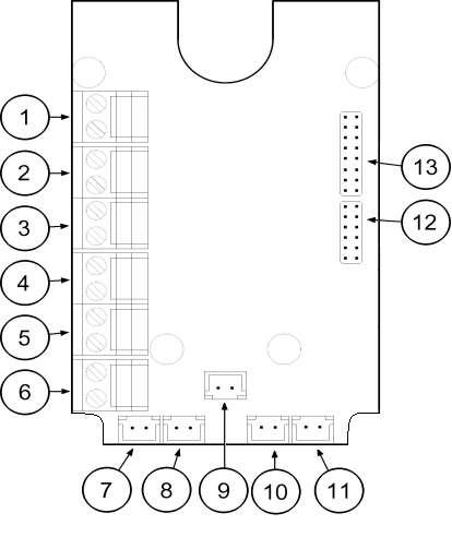
Description of Terminals, Connectors and Jumpers
Button controlled audio unit
Terminals | Connectors | ||||||||
|---|---|---|---|---|---|---|---|---|---|
1 | Audio unit bus | 7 | "Connection established" LED | ||||||
2 | ALARM, voltage activation | 8 | "Request received" LED | ||||||
3 | ALARM, contact activation | 9 | Microphone connector (optional) | ||||||
4 | CONFERENCE, voltage activation | 10 | Induction loop connector | ||||||
5 | CONFERENCE, contact activation | 11 | Speaker connector | ||||||
6 | ALARM 2 (set 2) | ||||||||
Configuration jumpers | Two LEDs (from the other side) | ||||||||
12 | ALARM and CONFERENCE input negation | 1. (yellow) | Request accepted | ||||||
13 | unused pins | 2. (green) | Connection confirmed | ||||||
Operation
The audio unit is controlled via a button or voltage.
A call is set up from the numbers defined in the 2N® Lift8 parameters. The first ALARM memory set includes parameters 011–016. The second ALARM memory set includes parameters 021–026. If set 2 is empty, the call is set up according to the set 1 parameters. This is set in parameter 029. If set 2 is empty and parameter 029 is not set, the call is not set up.
- If configured as an intercom, the audio unit can join a TRIPHONY call. Press the ALARM button to set the function. Connection is made to the audio unit that was the last to generate the ALARM function.
Bus Connection
Remove the terminal from the audio unit bus connector 1, connect the audio unit bus wires and replace the terminal. Keep the polarity.
Varování
- The audio unit is exclusively designed for the 2N® Lift8 audio unit bus connection. Connecting the audio unit other wires may lead to the audio unit damage or destruction.
- Be sure to keep the polarity to avoid malfunction.
Upozornění
- The audio unit is fed via a 2-wire bus. By disconnecting the wires you turn the audio unit off.
- Watch out for duplicate settings of the audio unit location.
ALARM and CONFERENCE Button Function
Machine room mode
The ALARM button in the machine room mode activates an alarm call to the selected parameter.
The CONFERENCE button activates connection with the other audio unit of one and the same elevator, which is indicated by a shining green LED. A repeated press ends the connection.
ALARM 2 helps end the rescue process.
Intercom mode
Set also the following to activate an audio unit in the intercom mode:
- ALARM parameter: "#" and the number (1–8) of the shaft in which the audio unit is located, e.g. "#1",
- Call confirmation by pick-up.
If another audio unit has activated the ALARM function to an audio unit in the intercom mode, the ALARM button can be pressed to pick up the call and repressed to terminate the call.
If the audio unit in the intercom mode has already been called, the ALARM button calls back (to the last called audio unit). Otherwise, the call will not be set up. The CONFERENCE button ends the call.
The CONFERENCE button activates connection with the other audio unit of one and the same elevator, which is indicated by a shining green LED. A repeated press ends the connection.
ALARM 2 helps end the rescue process and receive a Fireman call.
ALARM and CONFERENCE Connection
Button Control
Requirements
- The buttons must have a N/O or N/C contact that is not connected with any other circuits.
- None of the button outlets may be galvanically connected with any other electric circuit, no voltage may be connected to the terminals – only the contact can be connected.
- If the buttons have multiple contacts and one of them is connected to another circuit, the required standard insulation strength between the contacts must be maintained.
Voltage Control
Requirements
- DC voltage between 12 and 48 V.
- The voltage signal must be functional even at power outages.
Upozornění
- The yellow LED is on while the connection is being established (Request accepted).
- The green LED is on when the call has been confirmed (Connection confirmed).
Upozornění
- The audio unit cannot be configured for calling to the machine room audio unit of any shaft (1–8).
- Alarm 2 (021–026) is only used for ending the rescue process and receiving Fireman calls.
- The control room audio unit must be of the machine room type.
Induction Loop Connection
Installing the communicator, obey the applicable regulations in which it can be stipulated that the induction loop for deaf persons is a mandatory part of the lift cabin communicator. Insert the loop in the connector (10) with arbitrary polarity. Upon agreement, the loop can be part of the delivery including a 1 m long cable.
Requirements
- The induction loop must be placed behind a non-metal, non-magnetic cover in the control panel because the loop's magnetic field does not go through the non-metal lift panel.
- The induction loop must be marked with an appropriate pictogram (ear) and located as specified in applicable standards.
Rescue Process End
Press and hold the Alarm button for 3 s to end the rescue process.