2.4 Audio Unit - Machine Room
Description
The machine room audio unit is intended for installation in the machine room or as an intercom solution located in the reception. It has some distinctive features compared with the other types:
- The audio unit is equipped with a keypad.
- The keypad helps you select various functions and program the system.
- You can connect a handset to the audio unit for better acoustic properties in noisy environments.
- You can connect an external siren to the audio unit for incoming call signalling.
- You can configure the machine room audio unit to be shared by multiple lifts.
 |
Caution - upgrade
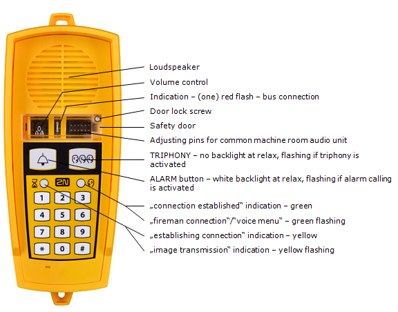
- The yellow, green and red LEDs are on (request received, connection confirmed and red LED under the glass) to indicate audio unit initialisation.
- The yellow and green LEDs flash to indicate audio unit upgrading. The red LED is permanently on.
- The ALARM pictogram (bell symbol) goes on upon upgrade and the audio unit is ready for use.
Operation
- This type of audio unit is operated by qualified people (lift maintenance staff, e.g.).
- Push the TRIPHONY button to activate voice communication with the other audio units of the same lift. Push and hold the button for over 2 seconds to activate communication with another lift (to display a voice menu and select the required lift number).
- Push the ALARM button to call the control centre, for example. The audio unit calls the numbers configured in the ALARM memory – set 2 (021–026). The ALARM button illumination (not required by default) helps you find and activate the audio unit easily in the dark.
- When you press the ALARM or TRIPHONY button, the function is called up immediately. Speak HandsFree or use a handset for better acoustic properties.
- Press
 for more than 2 s to display the voice menu.
Caution
- If no number is specified in the ALARM memory – set 2 (021–026), the audio unit dials the numbers defined in the ALARM memory – set 1 (011–016).
- Push the ALARM button to call the control room or machine room audio unit configured as an intercom.
- The ALARM and TRIPHONY buttons shine even at relax.
Before You Start
Requirements
- Connect a handset supplied by the manufacturer to the audio unit to avoid handset operation error.
Product Completeness Check
Check the product for completeness before installation.
- 1 audio unit
- 2 wall plugs
- 2 wall plug screws
- 7–8 jumpers for common machine room configuration
Mounting
The audio unit is typically mounted on a wall using the wall plugs and screws included in the delivery.
Electrical Installation
Description of Connectors
There are 3 connectors to the right under the cover:
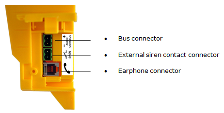 |
Figure: Machine Room Audio Unit Connectors
Tip
- Set the siren function in parameter 919, refer to Subs. 3.2 Table of Parameters (FW 2.1.0).
Address Configuration
There is a group of jumpers under the transparent front cover. Do not use any of them if the machine room is only intended for the given lift. The audio unit identifies itself as the machine room for the given lift.
If the machine room is to be shared by multiple lifts, configure the corresponding pins 1–8 for the lifts to share the machine room (numbered 1–8 from left to right 1–8).
Note
- This audio unit is always configured as the machine room and cannot have a different location.
- Group of 8 jumpers for address configuration: If the machine room is shared by multiple lifts, use one audio unit and configure several addresses using the included jumpers. The other audio unit types do not have this possibility!
Note
- Having set more addresses for the audio unit, press the TRIPHONY button to activate communication of the lift audio units with the lowest of the configured addresses.
Caution
- Avoid the audio unit address duplicity.
Bus Connection
Loosen the screws to the right and open the connector cover. There is just one connector under the cover: a bus connector. Pull out the terminal from the connector, connect the wires and replace the terminal. Make sure that the polarity is maintained.
Warning
- The audio unit is intended for 2N® Lift8 audio unit bus connection exclusively. Do not connect it to other wires to avoid its damage or destruction.
- Maintain polarity while connecting the audio unit to avoid audio unit error.
Caution
- The audio unit is powered via a 2-wire bus. Disconnection of these wires results in the audio unit switch-off.
Handset Connection
Order an additional handset for your audio unit. The handset is delivered including a cable with telephone end pieces.
Caution
- If the handset is not connected, the audio unit works in the HandsFree mode.
- A handset of a type other than that supplied by the manufacturer may not work.
Testing
Connect a handset and push and hold for over 2 s to display the voice menu for the function test. If the handset does not work, the voice menu will be played from the audio unit speaker.
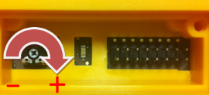
Volume Configuration
Open the protective door on the audio unit and adjust the volume using the trimmer.
 |
Caution
- Use the trimmer to set the best acoustic properties eliminating feedback.
- Volume configuration only works in the HandsFree mode.