3.1.4 Input and Output Pins
The Input / Output Pins tab shows the states of the device logic inputs and outputs.
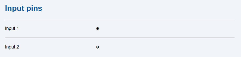 |
- Input 1 – 0 means that the input is deactivated (voltage below 2 V), 1 means that the IN1 input is activated (voltage above 4 V).
- Input 2 – 0 means that the input is deactivated (voltage below 2 V), 1 means that the IN2 input is activated (voltage above 4 V).
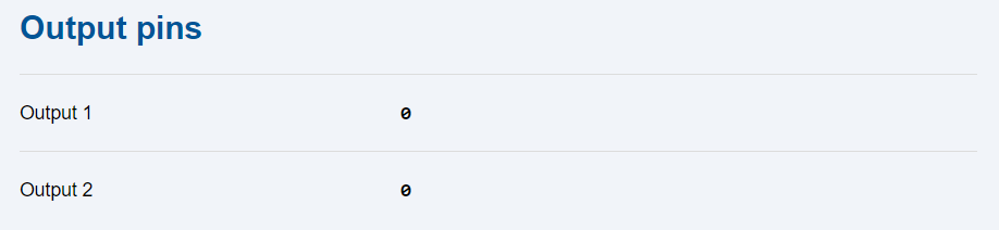 |
- Output 1 – 0 means that the relay is open (connected pins 1 and 2), 1 means that REL1 is closed (connected pins 2 and 3).
- Output 2 – 0 means that the relay is open (connected pins 4 and 5), 1 means that REL2 is closed (connected pins 5 and 6).