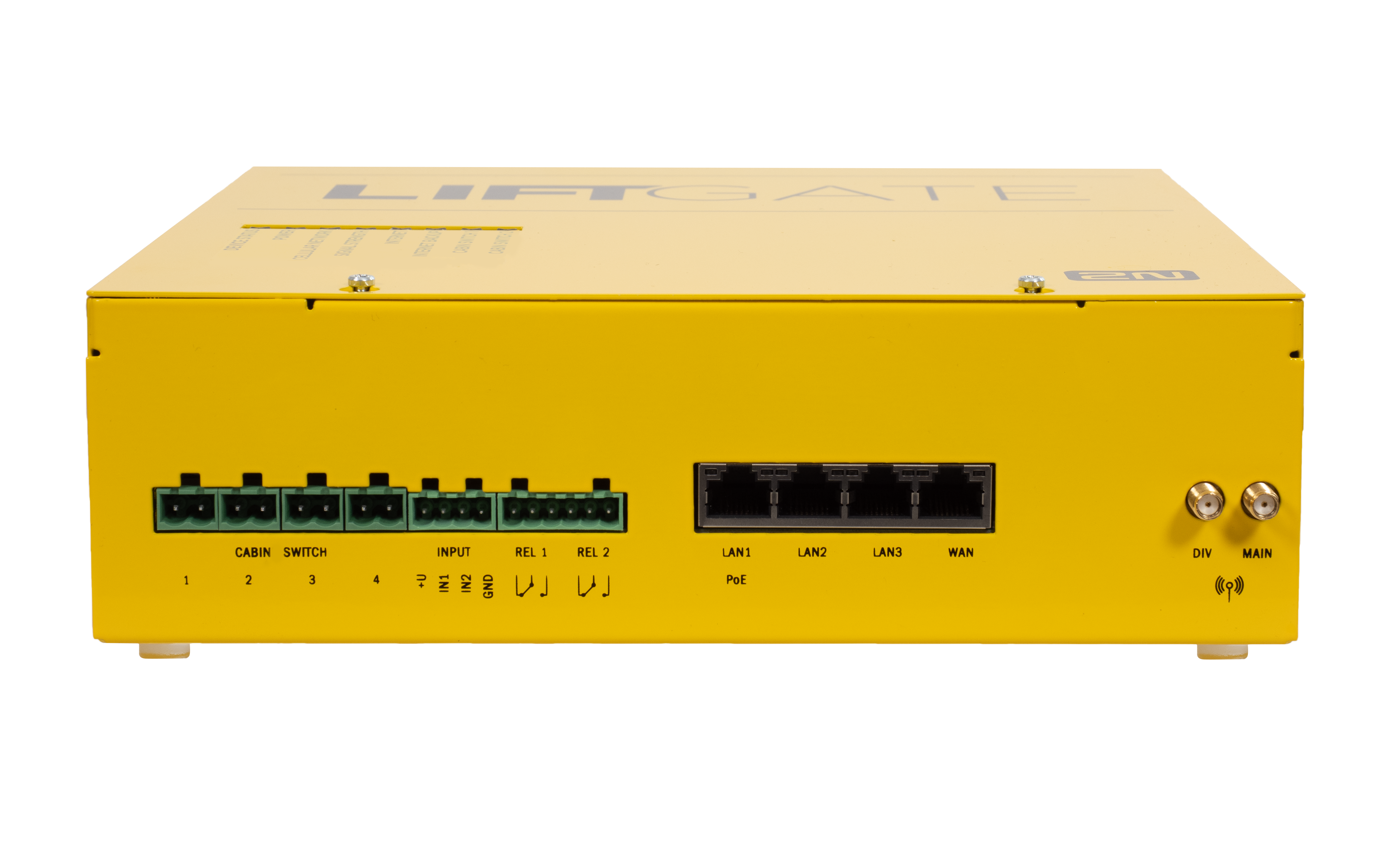
2.4 Overview of Connectors
Main Unit Connector Layout and Meanings
| ||
|---|---|---|
| CABIN SWITCH 1 & 2 | Cabin switch connection. | |
| INPUT 1,2 | User configurable inputs. | |
| REL 1, 2 | Relay with NO/NC contacts. | |
| LAN 1–3 | LAN connector, 10/100/1000BaseT, RJ-45; Ca5 or higher (recommended), LAN1 provides PoE 802.3af Class 2 (6.45 W max). | |
| WAN | WAN connector, 10/100/1000BaseT, RJ-45; Ca5 or higher (recommended). | |
| DIV | Optional LTE antenna with an SMA connector for a better signal quality. | |
| MAIN | Main LTE antenna with an SMA connector. | |
| SIM 1,2 | SIM card slots. The use of SIM 2 is optional. PIN-secured SIM cards can be inserted. Make sure that the PIN code is set in the configuration to put the device in operation. | |