11.3 2N® NetStar Installation Guide
Setting IP Address and Time
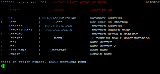
IP address
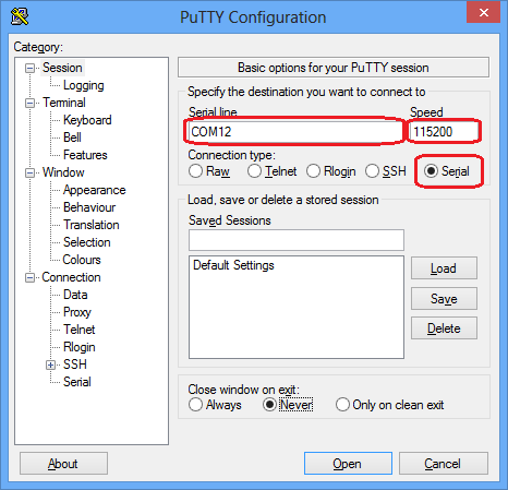
- Connect to 2N® NetStar with HyperTerminal tool
- Rate: 115200
- Flow control: None
- You can also use Putty
- Rate: 115200
- Serial line: set the COM interface number you are using for connection between your PC and 2N® NetStar
 |
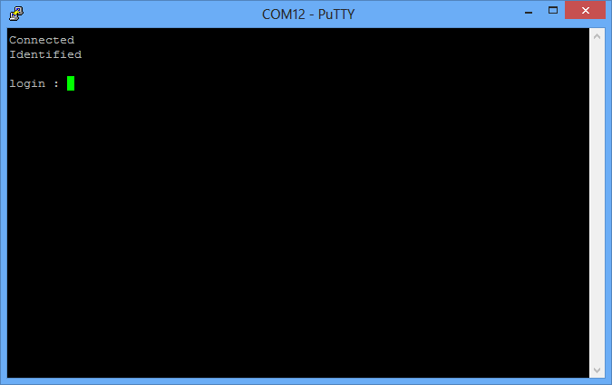
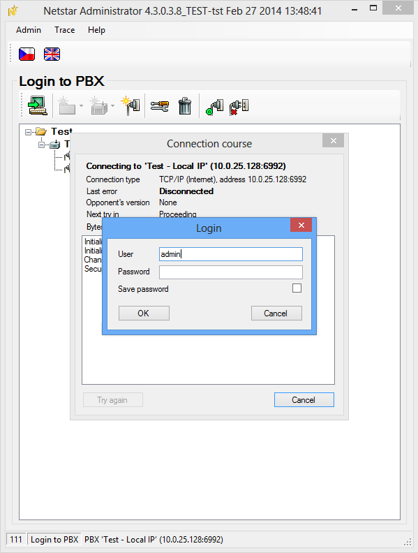
Once you are connected, press <ENTER> to get the login screen. The default login information is Admin and 2n. If there is a # character and no login request on the screen, type NsCon and push Enter for confirmation. The login request should get displayed.
 |
 |
 |
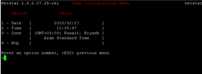
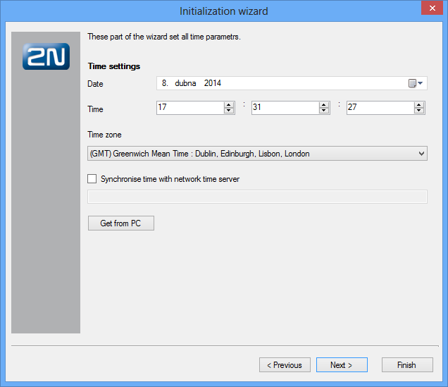
Time
When you are in the initial screen for time configuration, press 1 and 3. You will get into the Time setting menu. For correct configuration, push 3 to set the time zone and then enter the number according to your location. Then you can modify time and date using options 1 and 2.
You can also use the NTP server available in the LAN. Press option 4 to set the IP address or domain name of the NTP server (one DNS at least has to be set in the IP settings).
 |
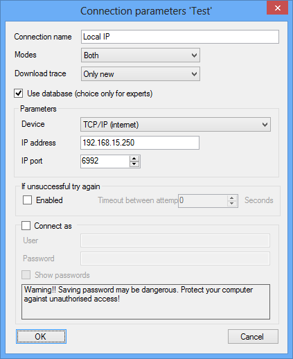
Connection of Configuration Tool to 2N® NetStar
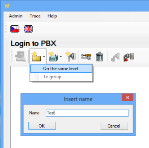
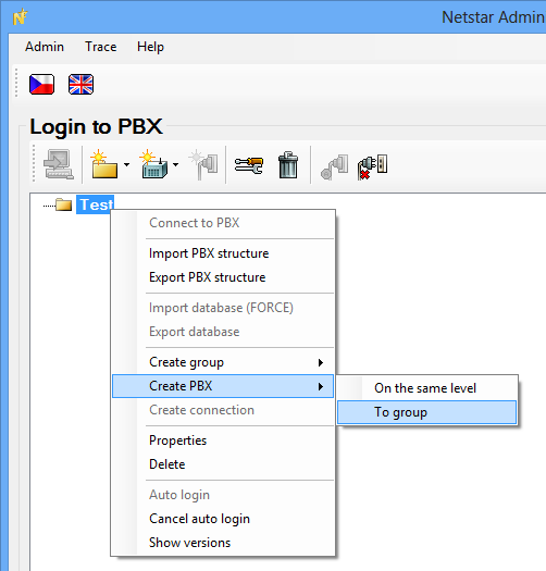
Start the 2N® NetStar configuration tool. If there is no connection to 2N® NetStar, create a new one.
Create a new group for the customer by choosing the Folder icon and the On the same level option and name the new group. In our case it is called Test.
 |
 |
 |
 |
 |
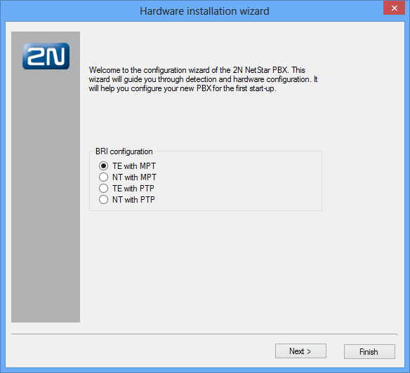
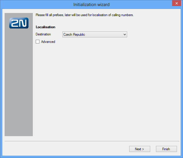
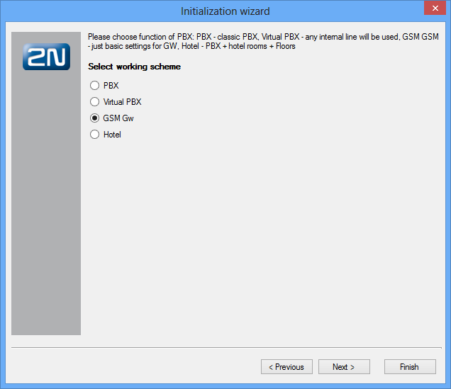
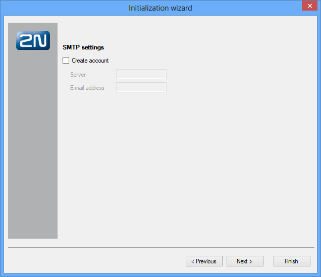
Configuration Wizard
The aim of the configuration wizard is to provide you with an easy basic installation. The ISDN BRI parameters are specified during configuration (click Next not to use ISDN BRI).
 |
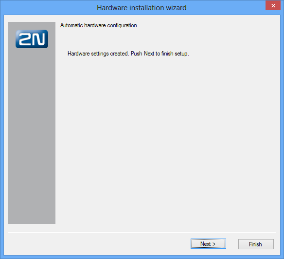
When the hardware detection is finished, click Next to continue.
 |
 |
 |
 |
 |
 |
 |
Interface Configuration
PRI ISDN
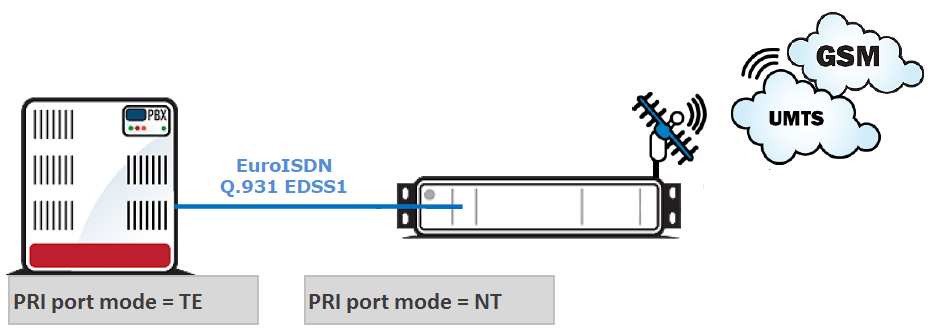 |
The most important aspect of PRI interface configuring is the configuration of the PRI line between 2N® NetStar and the PBX systems. The first information we need is the PRI interface configuration in the PBX. In case you are not sure about the PBX PRI port configuration, contact a person responsible for the PBX maintenance without delay. In our case, the PBX was connected to the PSTN and so the PRI port is configured as TE. For correct interconnection, 2N® NetStar has to be configured as NT. To do so you have to:
- Set PRI card jumpers – switch 2N® NetStar into the service mode. When the light goes off on the PRI card, remove the card from the rack and check the jumper configuration. For a correct jumper placing use the sticker on the PRI port.
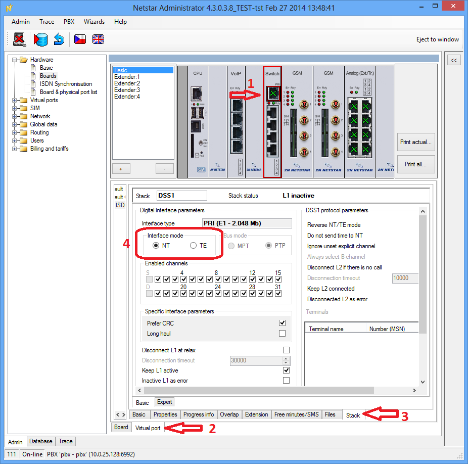
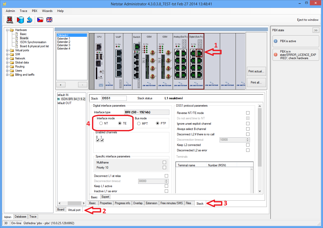
- Set correct communication protocol in the 2N® NetStar configuration tool. Go to the Boards menu in Hardware and choose the port to be configured. Set the Virtual port and Stack tabs for this port. When you are in the Stack menu, set the interface mode to NT.
 |
To apply your new configuration, save the changes to 2N® NetStar using the saving icon (or Ctrl+S). To configure the interface into the TE mode, take the same steps and set the jumpers and interface mode to TE.
BRI ISDN
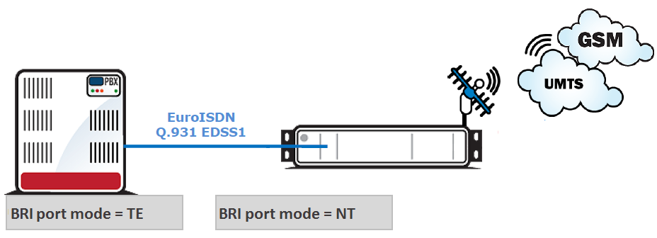 |
The most impotant aspect of BRI interface configuring is the configuration of the BRI line between 2N® NetStar and the PBX systems. The first information we need is the BRI interface configuration in the PBX. In case you are not sure about the PBX BRI port configuration, contact a person responsible for the PBX maintenance without delay. In our case, the PBX was connected to the PSTN and so the BRI port is configured as TE and Point-to-Point. For correct interconnection, 2N® NetStar has to be configured as NT and also PTP. To do so you have to:
- Set BRI card jumpers – switch 2N® NetStar into the service mode. When the light goes off on the BRI card, remove the card from the rack and check the jumper configuration. For a correct jumper placing use the sticker on the BRI port.
- Set correct communication protocol in the 2N® NetStar configuration tool. Go to the Boards menu in Hardware and choose the port to be configured. Set the Virtual port and Stack tabs for this port. When you are in the Stack menu, set the interface mode to NT and mode to PTP.
 |
To apply your new configuration, save the changes to 2N® NetStar using the saving icon (or Ctrl+S). To configure the interface into the TE mode, take the same steps and set the jumpers and interface mode to TE.
LCR Creation
The final configuration step is to create the LCR rules and configure the interfaces to work properly according to these rules.
Our task is to enable all outgoing calls to be passed to GSM and all incoming calls to be played the DISA welcome note or passed to the PBX IVR.
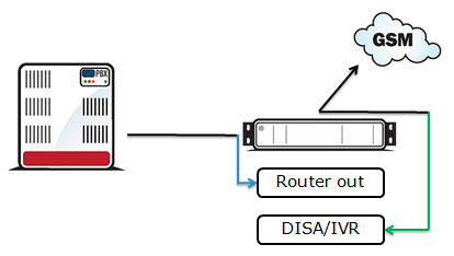 |
Outbound calls
We need to take three steps for outbound calls:
- Create a GSM bundle responsible for a correct and well-balanced use of all GSM modules.
- Create a router responsible for routing calls to the GSM bundle.
- Assign this router to a virtual port connected to the PBX.
Create GSM bundle
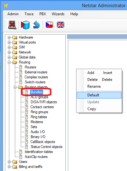
- Go to Routing – Routing objects – Bundles, click on the right mouse button and choose Default to create the default set of bundles. One of them is called GSM and filled with all GSM ports.
 |
- Make sure that the count of the GSM ports in the GSM bundle matches the count of ports available in 2N® NetStar.
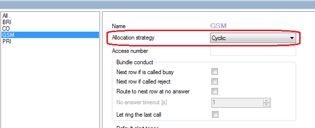
Configure the bundle – set the allocation strategy to Cyclic.
Create router
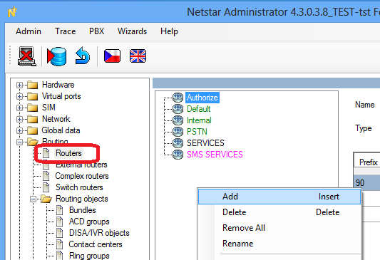
- Go to Routing – Routers, click on the right mouse button and choose Add.
 |
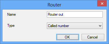
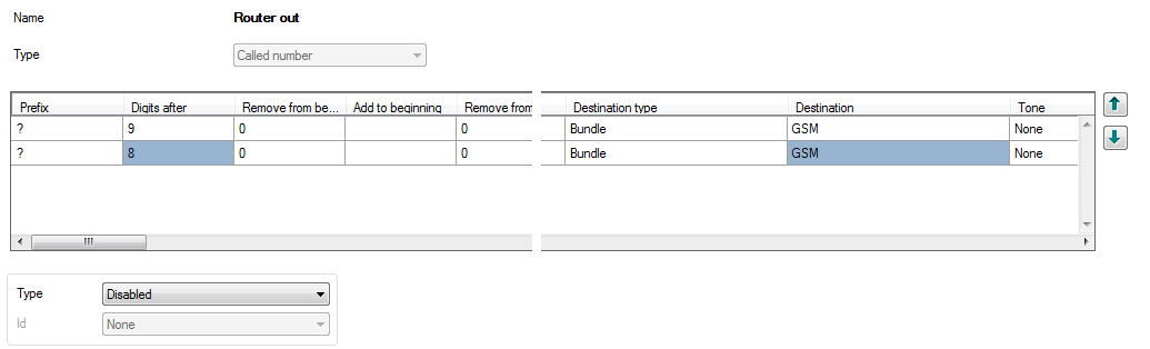
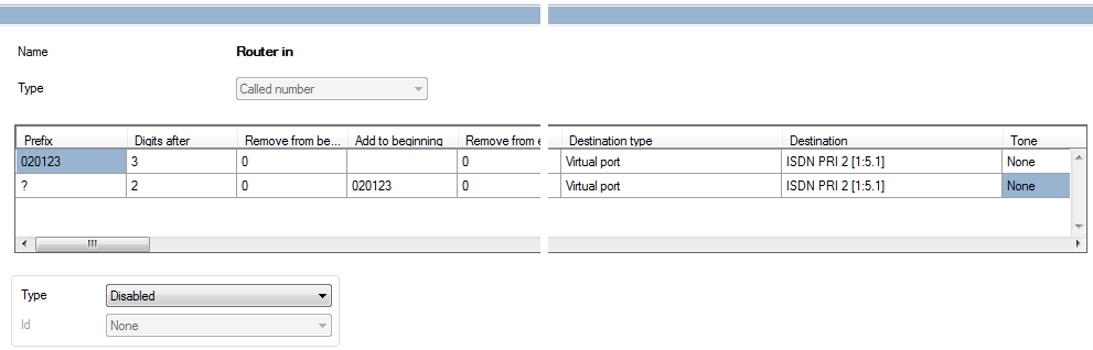
Fill in the router name and keep the Called number type selection.
- Add 2 rows as shown in the figure below (click on the right mouse button and choose Add).
 |
- Go to the Hardware – Boards and choose a port connected to the PBX.
- On the bottom side of the configuration tool choose the Virtual port tab, then Properties and finally Routing.
- On the Routing tab set From port, Type to Router and Id to your router.
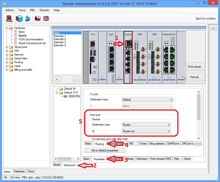 |
Save your new configuration to 2N® NetStar using the icon.
Now 2N® NetStar is properly configured to pass calls from the PBX to GSM or PSTN through a bundle of GSM ports.
Inbound calls
We need to take two steps for inbound calls:
- Create an incoming router responsible for routing calls into the connected PBX and assign the router to the virtual port through which 2N® NetStar is connected to the PSTN (GSM ports).
- Set the DISA function for processing incoming calls.
Create router
- Go to Routing – Routers, click on the right mouse button and choose Add.
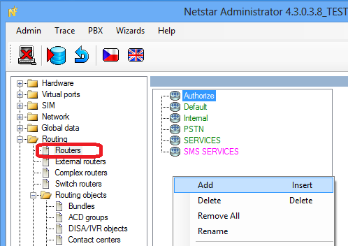 |
- Fill in the router name and keep the Called number type selection.
Suppose that the PBX PRI port cannot be re-programmed. In this case you have to send a call request in the same format as the PSTN. Suppose the company number is 020123xxx. When DISA passes the digits to your router, you have to take into account that the user can dial the number as a full PSTN number (first line) or as a short extension number (second line). In the latter case, you have to add 020123 to make the PBX receive the number as from the PSTN. In both the cases, the call will pass to the PRI interface that is connected to the PBX.
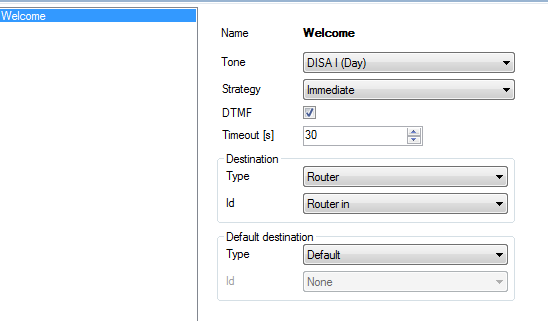
Configure DISA for incoming calls
- Go to Routing – Routing objects – DISA, click on the right mouse button and choose Add.
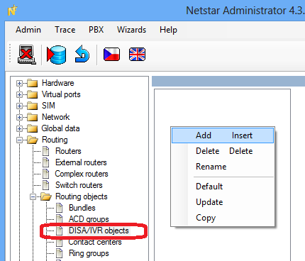 |
Name your new DISA and set it as shown in the figure below.
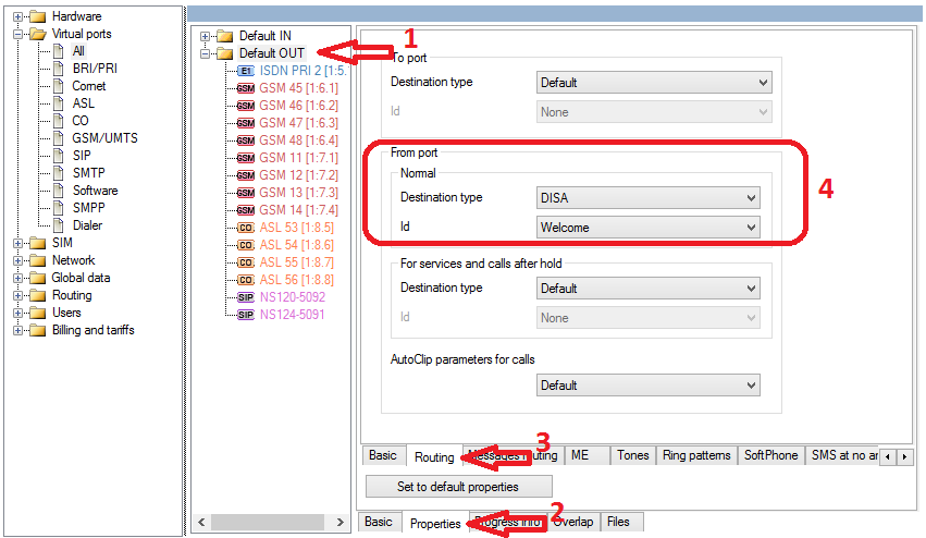
Assign DISA for all GSM channels
- Go to Virtual ports – Default OUT – Properties – Routing.
- On the Routing tab set From port, Type to DISA and Id to your new DISA.
Save your new configuration to 2N® NetStar using the icon.
 |