2.5 Installation - Universal version
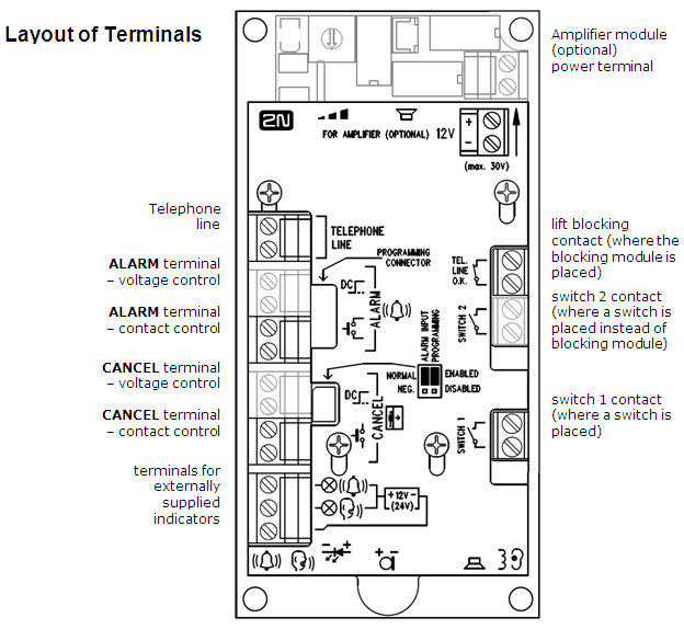
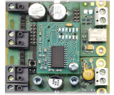
Layout of Terminals, Jumpers and Connectors
You can see on the picture below layout of terminals.
 |
Note
- The terminals are accessible without removing the cover.
Jumper Settings
Left-hand jumper (ALARM INPUT) | Right-hand jumper (PROGRAMMING) | ||
inverted ALARM input | disabled PROGRAMMING | ||
up (NORMAL) | closing contact or voltage connection activation | up (ENABLED) | enabled |
down(NEG.) | breaking contact or voltage disconnection activation | down(DISABLED) | disabled |
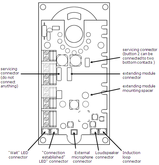
Connectors accessible after cover removal
 |
Tip
- To access connectors at the bottom edge of the board without cover removal, just loosen cover screws gently and slide the cover upward. Applies to HW version 7 and higher, when amplifier module is not mounted.
Description of terminals
Telephone line | Polarity does not matter. Can be connected directly to a private telephone network (PSTN), PBX or GSM gateway line. CAUTION – more than one unit may not be connected to a single line!!! | ||
ALARM | voltage control *) | 12 – 24V DC voltage,any polarity | Emergency call activation |
contact control | switching or breaking contact | ||
CANCEL | voltage control *) | 12 – 24V DC voltage,any polarity | Emergency call deactivation |
contact control | switching or breaking contact | ||
Indicator connecting terminals *) | Indicators (backlit pictograms), max. 24 V / 2× 200 mA, supplied from an external power supply, the connection layout must be maintained. | ||
External microphone connector | External microphone is available on request. Switching between onboard and external microphone is automatic (external microphone is detected). ***) | ||
External loudspeaker connector | For a request, loudspeaker can be equpped with cable. In this case, it is connected here.
| ||
Induction loop connector | The induction loop is not a part of standard packing. It has to be placed behind a non-metal, non-magnetic cover in the control panel because the magnetic field of the induction loop cannot go through the metal lift control panel. Notes:
| ||
Lift blocking contact *) **) | In the event of telephone line failure, the contact opens, the lift goes to the nearest floor and the door opens. The lift should not go on until the telephone line function is restored. | ||
Switch 2 contact *) **) | The switches can be used as needed and are remotely controlled using a digital password (DTMF). The switches are not designed for 230V! | ||
Switch 1 contact *) **) | |||
*) These terminals are safely electrically isolated from the telephone line.
**) Extending module terminals. The lift blocking module can be mounted only if switch 2 is absent.
***) Applies to boards of version 5 and higher. These boards has both onboard microphone and the connector for external one.
ST Telephone Line Connection
The ST works regardless of polarity or line parameters in a wide range (see Technical Parameters). The line is connected to the LINE terminals. A great advantage of the ST is that it needs no other power supply for its operation. Details on the ST connection to PSTN, PBX and GSM gateway lines are available in the "ST Connecting Options" section.
ALARM Button Connection – Button control
Safety
- Make sure that the button is safe – the isolation distance must be 1.5 mm at least and the break-down voltage may not fall below 1500V. The button contacts may not be connected to any other circuits. In case the above mentioned conditions cannot be met, use voltage control.
- Connect the button contacts to the ALARM terminal, leaving it in the low position.
- The button can have both the switching and breaking contacts. With the breaking contact, switch the ALARM INPUT jumper into position NEG.
ALARM Button Connection – Voltage control
Tip
- 12 to 24V DC voltage of any polarity can be applied. However, the source must be backed-up in case of power outage.
- Slide the ALARM terminal out and put it in the upper position to ensure the required isolation against the telephone line circuits.
- Activation is controlled by voltage connection/disconnection. If voltage disconnection activation is used, switch the ALARM INPUT jumper into position NEG.
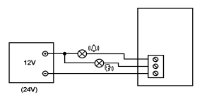
Indicator Connection
Basic connection
In this type of connection, any indication elements can be used (backlit pictograms, e.g.). An external power supply provides a sufficient indicator intensity.
 |
Requirements
- a 12 – 24 V power supply (backed up if necessary)
- steady state current of 200 mA maximum (incandescent lamps may be connected)
- Both indicators must be connected!
Warning
- Remember to keep the correct power supply polarity!
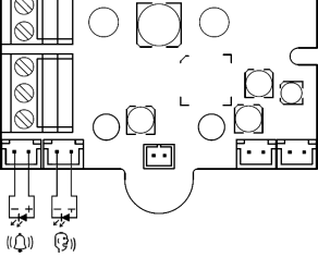
LEDs mounted onto the ST electronics board
Nothing is connected in this case.
For this purpose, use light guides to conduct light to two panel holes (refer to Section Mounting of Panel with ST Electronics). These light guides are not included in the standard accessories.
Cable-connected LEDs (optional accessories)
Cable-connected LEDs can be used where backlit pictograms are unavailable. The LEDs are not included in the standard accessories, they are available as a separate delivery or as part of a client-defined solution. The LEDs have the diameter of 5 mm and a very high luminance.
 |
Requirements
- Keep the LED polarity (see the cover printing)
- Keep colors: request confirmation – yellow, connection confirmation – green
Note
- The PCB LED is not on in this type of connection.
CANCEL Input Connection (Door Control, Optional)
Caution
- The door switch or door opening signal must indicate an open door only if both the internal and external lift doors are open and the lift car can be left safely.
Note
- If the CANCEL input is used, be sure to program parameter 914 for a period longer than the maximum lift running time (i.e. while the door is closed). If parameter 914 is set at 0, it is useless to connect the CANCEL input.
Switch control
Safety
- The CANCEL input is connected with the telephone line circuits. Therefore, the air distance between the switch and the other lift parts must be 1.5 mm at least and the break-down voltage may not be less than 1500V. The switch contacts may not be connected to any other circuits. In case the above mentioned conditions cannot be met, use the voltage control.
- Connect the switch to the CANCEL terminal, leaving it in the low position.
- By default, the ST is set for a switch that is closed when the door is open. If the switch is closed when the door is closed, select parameter 916 – see Programming.
Voltage control
DC voltage of any polarity ranging between 12 and 24V can be applied.
- Slide the CANCEL terminal out and switch it in the upper position to ensure the required isolation against the telephone line circuits.
- In the event of voltage disconnection activation select parameter 916 – see Programming.
- By default, the ST is ready to accept a sensor that applies voltage when the door is open. If it gives voltage when the door is closed, select parameter 916 – see Programming.
Caution
- If voltage presence indicates that the door is closed, this source must be backed-up against power outage.
Induction Loop Connection
The regulations that apply to communicator installations may require a mandatory loop for persons with defective hearing in the lift cabin. In that case, connect the loop to the connector with any polarity as shown in the drawing. The loop including a 1 m long cable can be part of the delivery if agreed so in advance.
 |
Requirements
- The induction loop has to be placed behind a non-metal, non-magnetic cover in the control panel because the magnetic field of the induction loop cannot go through the metal lift control panel.
- The induction loop has to be labelled with an appropriate pictogram (ear) and placed according to applicable standards.
Installation of Extending Modules
Extending Modules Location
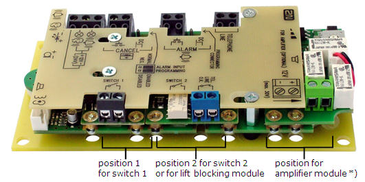 |
*) Amplifier module cam be mounted directly to the main board (inserted into margin slots) as shown above, if mainboard HW version is 7 or higher (model 2011).
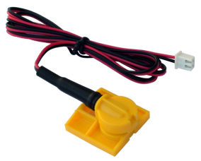
Switch Installation
Universal switch module (order No. 913648E) can be installed (before ST mounting!) into position 1 or 2 without removing the ST cover. Having inserted the module into the motherboard margin slots, tighten the two screws (through the panel cutouts).
 |
Caution
- Be sure to tighten both the screws!
Warnings
- In reality, the "Contact" is a semiconductor switch of the ON-state resistance of about 0.5 Ω. Switching voltage values lower than 9V may bring troubles – the switch function cannot be, e.g., tested using a common ohmmeter because it is used for small voltage only.
- The maximum switched current is 1 A. The switch is protected with a resettable fuse against higher current values
- The allowed voltage is from 9 to 24 V, both DC and AC. The switch is equipped with overvoltage protection against voltage peaks.
- The switch "contact" is safely electrically isolated from the telephone line, yet designed for weak-current applications only. It cannot be used for mains voltage of 230 V or 120 V.
Lift blocking module Installation
Lift blocking module (order No. 913649E) can be installed (before ST mounting!) into position 2 without removing the ST cover. Having inserted the module into the motherboard margin slots, tighten the two screws (holes in the panel).
 |
Caution
- Be sure to tighten both the screws!
Module function
The contact is closed when the telephone line is OK.
Cautions
- The module responds to the telephone line disconnection with an up to 2 minutes' delay.
- The maximum switched current is 1 A. The allowed voltage value is up to 24 V. It is a mechanical contact (relay)).
Warning
- The module "contact" is safely electrically isolated from the telephone line, yet designed for weak-current applications only. It cannot be used for mains voltage of 230V or 120V.
Extending module Installation
The extending module (Part No. 913647E) allows you to record and play your own voice messages (the lift cabin address, e.g.). Typically, it is integrated in ST as Part No. 913641 or 913643. But it can also be mounted additionally as described below.
Note
- Before installing an extending module produced earlier, check it for compatibility with your ST! Modules No.913402E are very similar, but are equipped with a diagnostic connector on the upper side. They are not fully software-compatible and, if installed, result in the ST error.
Installation steps
- Loosen 4 screws and remove the electronics cover.
- Put the module on the connector in such a way that you can see the column thread through the module corner hole.
- Fit the module with the attached M3 screw.
- Replace the cover, screwing it into position.
 |
Amplifier Module Installation
Please follow the manual enclosed to amplifier module.