2.6 Installation - Compact Version
Caution
- Be sure to connect the wires before wall mounting. The connectors are separable – remove them, connect the wires, tighten the screws and replace the connectors.
Safety Precautions
- The product is connected to a telephone line where life-endangering voltage may occur, during storms in particular. Be sure to install the ALARM button in such a manner that the user cannot get in touch with the wires and can be protected against electrical accident. The minimum isolation distance must be 1.5 mm and/or the minimum breakdown voltage must be 1,500 V – for the used button too!
- Make sure that the cables cannot get in contact with sharp edges during installation to avoid insulation damage.
- Check after installation that the isolation distance of 1.5 mm is kept everywhere. Use an insulation meter if possible.
- The manufacturer shall not be held liable for any installations made in conflict with the User Manual or the Appendix thereto.
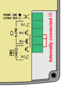
Terminal Description (elderly HW)
 |
Terminal Description (newer HW)
Tip
- The above mentioned safety precautions need not be observed in case your ST unit is connected to a 2N® EasyGate GSM gateway installed near the communicator.
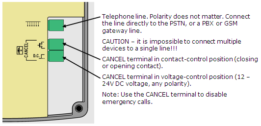
Terminals
Telephone line / LN bus | Refer to ST or LN User Manual | ||
ALARM terminals | DC = voltage control *) | 5 – 24Vdc, any polarity | Emergency call activation |
N.O. = N/O contact | normally open contact | ||
N.C. = N/C contact | Normally closed contact WARNING! If unused, the contact should not be opened! | ||
CANCEL terminal | voltage control *) | 5 – 24Vdc, any polarity **) | Emergency call deactivation upon door opening |
contact control | any contact **) | ||
*) For safety reasons, these terminals are electrically isolated from the telephone line.
**) You need not do anything to activate *ALARM if you keep the factory settings. For deactivation, voltage application or contact closing is necessary. To change the settings use parameter 916 for ST and the rotary switch for LN.
Accident Hazard
- Make sure that the button is safe, i.e. that the minimum isolation distance is 1.5 mm and the minimum breakdown voltage value is 1,500 V. The button contacts may not be connected to any other circuits. If any of the above conditions cannot be met, use voltage control.
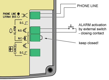
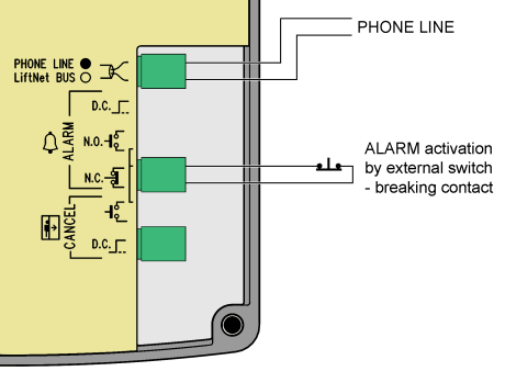
- You can use an N/O or N/C button or both.
- Refer to the rear cover for internally connected terminals.
 |
ALARM Button Connection with N/O Contact
 |
 |
Notes
- The ALARM button mounted on the cover is still functional when an external button is connected.
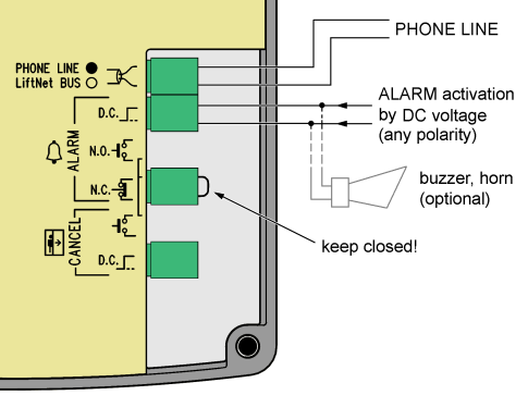 |
Voltage Activation
Notes
- 5 - 24 dc voltage of any polarity can be used. Make sure that the power supply is backed up properly.
- Where activation from multiple places is necessary, voltage control can be combined with buttons.
- A buzzer or horn can be connected in parallel, see the figure to the right.
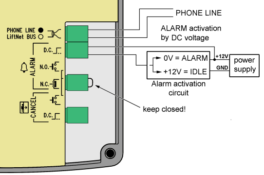 |
Inversion Voltage Control
The figure to the right shows a configuration where voltage is present and activation is caused by non-presence of voltage.
Warning
It is impossible to connect multiple devices to a single line!!!
Tip
- The Compact version is very easy to install because the ALARM button, backlit picrograms and induction loop are part of the product. All you have to do is connect a telephone line. The CANCEL input connection is optional.
 |
Telephone Line Connection
ST works regardless of polarity and/or line parameters in a wide range (see the Technical Parameters section). It is connected via the LINE terminals. A great advantage is that ST requires no additional power supply for operation. For details on ST connection to PSTN, PBX and GSM gateway lines refer to the ST Connecting Options section.
CANCEL Input Connection (Door Contact, Optional)
The connection is the same as with the Universal version. Follow the instructions included in the Installation – universal version section, The only difference is that the terminal is in the upper position for contact control and in the low position for voltage control as printed on the rear cover at the terminals.
Induction Loop Connection
It is unnecessary to install the induction loop. It is integrated in the product, located to the right in the window area and labelled with the prescribed blue pictogram.
Mounting Completion
Having connected the wires, you can complete the ST wall mounting. The mounting is easier if you can access the cabin wall from the outside. In this case, the screws are inaccessible from the cabin and ST cannot be stolen. If the cabin wall is accessible from the outside, follow the instructions in item a) or b). If not, follow item c).
 |
- If the cabin wall is thin (stainless steel sheet), use four 8 mm long M4 screws and fan washers from the accessories. Apply ST on the pre-drilled place and screw the M4 screws including the washers from the rear panel side.
- If the cabin wall is thick (up to 20 mm – laminated chipboard, e.g.), use four headless 30 mm long M4 screws from the accessories. First screw them into the ST back holes and tighten. Then get the set through the pre-drilled holes and apply the fan washers and nuts from the rear.
- If the cabin wall is inaccessible from the rear, follow instructions on the next page. TIP: If you have pre-drilled corner holes, find four headless M4 screws of the length of 30 mm in the package. Drive the screws into the holes on the rear side of the audio unit and tighten as mentioned in item b) above. Though unprovided with nuts, the screws fix the product reliably, preventing it from sliding or turning.
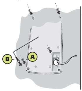
Mounting Completion – withour rear access
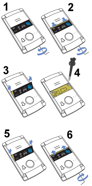 |
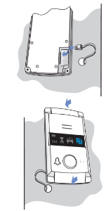
- Insert the hex wrench (included in the delivery) in the bottom unit edge hole; turn left about 10 times until it puts up resistance.
- The window slides down by itself or with little assistance, showing its upper brim.
- Tilt the window forwards and remove.
- Now you have access to two holes in the window corners. Put ST (including the connected wires) on the pre-drilled lift cabin wall. Drive and tighten the included screws for plywood, chipboard, laminated plastic etc. wall mounting or short M4 screws with fan-shaped washers (intended for metal plate mounting with pre-drilled M4 threaded holes).
- Replace the window.
- Insert the hex wrench (included in the delivery) in the bottom unit edge hole, turn right about 10 times until the window slides under the panel edge and tighten applying light force.