2.3 Lift Cabin Audio Unit - Compact
Description
This audio unit is designed for lift wall mounting. No opening has to be cut for installation since the audio unit is surface mounted.
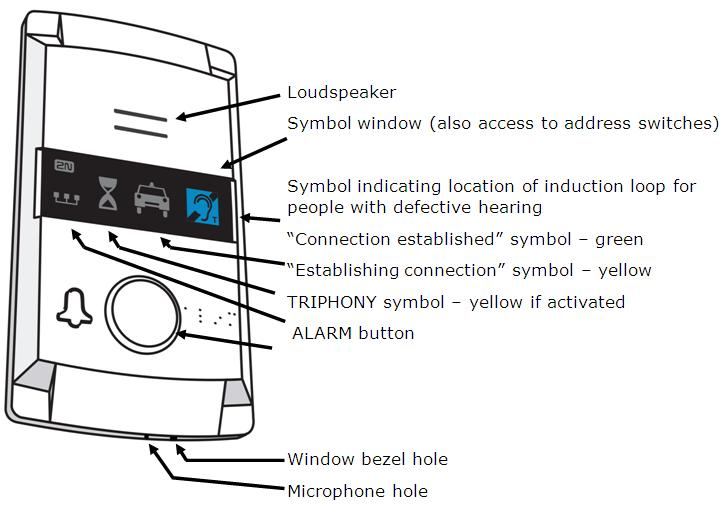 |
Figure: Description of Lift cabin Audio Unit – Compact
Operating instructions
- Activate by pressing the ALARM button. The "Wait" symbol lights up and, once communication has been established, the "Connection established" symbol comes on.
- To activate the TRIPHONY mode press the button on the shaft or machine room audio unit for which the same address has been set.
Before You Start
Requirements
- The lift wall surface must be perfectly flat.
- The mounting place must comply with applicable regulations (e.g. standard ALARM button elevation and relative distance from other lift buttons).
Product Completeness Check
Check the product for completeness before installation please:
- 1 Compact audio unit
- 1 window with printing
- 2 terminals inserted in the back side connector
- 1 long hexagonal 2mm round-head wrench
- 4 M4×8 screws
- 4 headless M4×30 screws
- 4 M4 nuts
- 4 fan washers
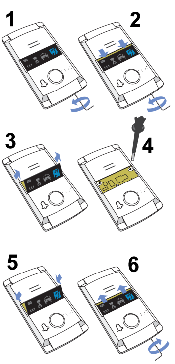
Address Setting
The audio unit is set as lift cabin 1 by default. If you want to change the address, you are recommended to do so before mounting.
 |
Instructions
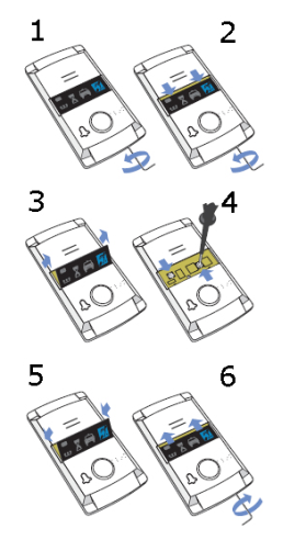 |
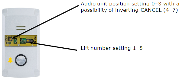
Figure: Address Setting for Lift Cabin Audio Unit – Compact
- Insert the hex wrench (included in the delivery) in the bottom unit edge hole; turn left about 10 times until it puts up resistance.
- The window slides down by itself or with little assistance, showing its upper brim.
- Tilt the window forwards and remove.
- Set the audio unit address using a screw driver:
| left rotary switch: 0 or 4 … machine room 1 or 5 … shaft bottom 2 or 6 … lift cabin 3 or 7 … lift cabin ceiling | right rotary switch: 1–8 = lift number |
Caution
- Right rotary switch: 1 to 8 print, i.e. set 1 for lift number 2 etc.
Note
- Left rotary switch: If you use the CANCEL input and the contact is open with the door closed, set the left switch into one of positions 0 to 3; if the contact is closed with the door closed, set the left switch into one of positions 4 to 7.
- Replace the window.
- Insert the hex wrench (included in the delivery) in the bottom unit edge hole, turn right about 10 times until the window slides under the panel edge and tighten applying light force.
Mounting
Just drill holes into the lift cabin wall as indicated in the drawing below or as printed 1:1 on the audio unit package. The larger hole is intended for cable passage. Round the hole edges to avoid cable damage!
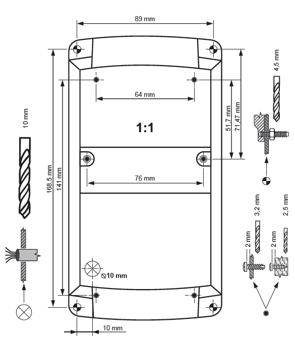 |
Figure: Mounting Hole Dimensions for Lift Cabin Audio Unit Top - Compact
Note: The two 2.5 mm large holes in the window area are used where the mounting panel rear is inaccessible. The 2.5 mm diameter is suitable for all wall mounting options using plywood, chipboard, laminated plastic etc. with the aid of the screws included. For front metal panel wall mounting drill M4 threaded holes.
Further steps can only be made after connection and are thus included in the next section.
Electric Installation (Earlier HW)
Caution
- Be sure to connect the wires before wall mounting. The connectors are separable – remove them, connect the wires, tighten the screws and replace the connectors.
Connectors
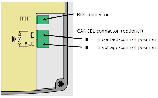 |
Figure: Connectors of Lift Cabin Audio Unit – Compact
Electric Installation (Later HW)
Terminals
Telephone line / LN bus | Refer to ST or LN User Manual | ||
ALARM | DC = voltage control *) | 5 – 24Vdc, any polarity | Emergency call activation |
N.O. = N/O contact | Normally open contact | ||
N.C. = N/C contact | Normally closed contact WARNING! If unused, the contact should not be opened! | ||
CANCEL | voltage control *) | 5 – 24Vdc, any polarity **) | Emergency call deactivation upon door opening |
contact control | any contact **) | ||
*) For safety reasons, these terminals are electrically isolated from the telephone line.
**) You need not do anything to activate ALARM if you keep the factory settings. For deactivation, voltage application or contact closing is necessary. To change the settings use parameter 916 for ST and the rotary switch for LN.
Connectors
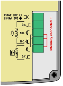 |
Figure: Connectors of Lift Cabin Audio Unit – Compact (Later HW)
Warning
- Make sure that the button is safe, i.e. that the minimum isolation distance is 1.5 mm and the minimum breakdown voltage value is 1,500 V. The button contacts may not be connected to any other circuits. If any of the above conditions cannot be met, use voltage control.
- You can use an N/O or N/C button or both.
- Refer to the rear cover for internally connected terminals – see Fig. 2.13.
ALARM Button Connection with N/O Contact
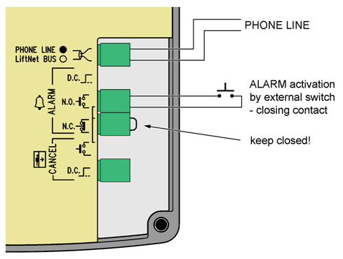 |
Figure: ALARM Button Connection with N/O Contact
ALARM Button Connection with N/C Contact
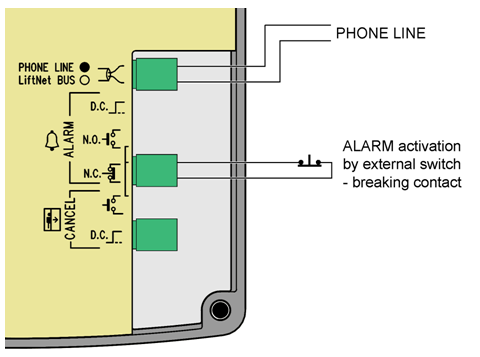 |
Figure: ALARM Button Connection with N/C Contact
Note
- The ALARM button mounted on the cover is still functional when an external button is connected.
Voltage Activation
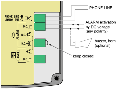 |
Figure: Voltage Activation
Caution
- 5 - 24 dc voltage of any polarity can be used. Make sure that the power supply is backed up properly.
- Where activation from multiple places is necessary, voltage control can be combined with buttons.
- A buzzer or horn can be connected in parallel, see the figure to the right.
Inversion Voltage Control
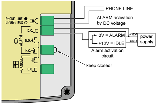 |
Figure: Inversion Voltage Control
The figure to the right shows a configuration where voltage is present and activation is caused by non-presence of voltage.
Bus Connection
The connection polarity is arbitrary.
Warning
- Connection to different, e.g. higher-voltage, cables leads to damage or destruction of the audio unit.
Caution
- Avoid the audio unit address duplicity.
CANCEL Input Connection (Door Contact, Optional)
This input helps cancel a rescue request if the lift is fully functional. When the ALARM button is pressed, the system waits for a pre-programmed period of time, which is a little longer than the maximum lift running time. If the lift is functional, it arrives in the required station within this timeout and opens the door. In that case, the rescue request is cancelled. If the door fails to open, the request is accepted.
Make sure before installation that the "door open" signal is available in the lift cabin.
Requirements
- In double-door lifts, the signal has to be active only if both the doors open successfully and let the people out.
- The door position signal has to work even in the case of power outage.
Contact control
Requirements
- None of the CANCEL terminals may be connected electrically with any other electrical circuit and a voltage source other than the contact.
Instructions
- Connect the CANCEL terminal into upper position.
- Make sure that the switch position matches the door contact configuration (open or closed when the door is closed) – see Address setting.
Voltage control
Requirements
- DC 12 to 48V voltage
Instructions
- Connect the CANCEL terminal into lower position.
- Make sure that the switch matches voltage presence or absence when the door is closed – see Address Setting. Voltage presence corresponds to a closed contact; voltage absence means an open contact.
Warning
- Ignoring the instructions above may lead to product damage.
Note
- Remember to program delayed calling to make the CANCEL connection work successfully.
Mounting Completion
Connect the wires before wall mounting. The connectors are separable – remove them, connect the wires, tighten the screws and replace the connectors.
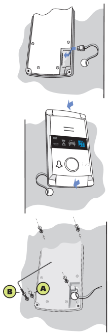 |
Figure: Lift Cabin Audio Unit – Compact Mounting
Mounting the audio unit from the outer lift cabin wall is easier. In that case, no screws are accessible from the lift cabin and the audio unit cannot be stolen. If the cabin wall is accessible from the outside, follow the instructions in item a) or b). If not, follow item c).
- If the lift cabin wall is thin (stainless steel sheet), seek four 8 mm long M4 screws and fan-shaped washers in the accessories.
- If the lift cabin wall is thick (up to 20 mm – laminated chipboard), seek four headless, 30 mm long M4 screws. Screw them into the unit backside using the wrench included in the delivery and tighten properly. Then push the assembly through the pre-drilled holes, insert the fan-shaped washers from the back and screw in the nuts.
- If the lift cabin wall is inaccessible from the rear, follow instructions on the next page.
TIP: If you have pre-drilled corner holes, find four headless M4 screws of the length of 30 mm in the package. Drive the screws into the holes on the rear side of the audio unit and tighten as mentioned in item b) above. Though unequipped with nuts, the screws fix the product reliably, preventing it from sliding or turning.
Induction loop connection
The induction loop for people with defective hearing is included in the product, no other loop is needed.
Mounting Completion – without Rear Access
 |
- Insert the hex wrench (included in the delivery) in the bottom unit edge hole; turn left about 10 times until it puts up resistance.
- The window slides down by itself or with little assistance, showing its upper brim.
- Tilt the window forwards and remove.
- Now you have access to two holes in the window corners. Put unit (including the connected wires) on the pre-drilled lift cabin wall. Drive and tighten the included screws for plywood, chipboard, laminated plastic etc. wall mounting or short M4 screws with fan-shaped washers (intended for metal plate mounting with pre-drilled M4 threaded holes).
- Replace the window.
- Insert the hex wrench (included in the delivery) in the bottom unit edge hole, turn right about 10 times until the window slides under the panel edge and tighten applying light force.