2.2 Lift Cabin Audio Unit - Universal
Description
The user is not in a direct contact with this product.
The controls and indicators depend on the lift cabin control panel type. The indicators (e.g. bulbs or LEDs) are working in accordance with the applicable standards.
Address Setting – see the Installation section for details.
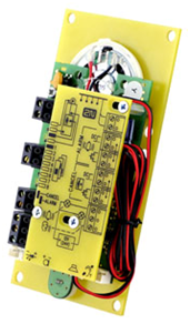 |
Figure: Lift Cabin Audio Unit – Universal
Before You Start
Requirements
- The panel has to be installation-ready, including loudspeaker perforation.
- The panel has to be equipped with the following obligatory elements:
- ALARM button;
- Backlit symbol "Request accepted";
- Backlit symbol "Connection established".
- The above mentioned elements have been located as required by applicable regulations.
- There must be free space of at least 65×130×20 mm behind the panel.
Product Completeness Check
Check the product for completeness before installation please:
- 1 board with electronics
- 4 terminals slid on the board pins, see the photo
- 4 jumpers slid on the board pins, see the cover print
- 1 mounting panel
- 1 directly/cable-connected loudspeaker
- 1 directly/cable-connected microphone
- 1 printed cover
- 5 tightening strips
Mounting
Main Board Mounting
This audio unit is mounted behind the lift control panel. Typically, the panel is ready for installation as shown in the drawing below:
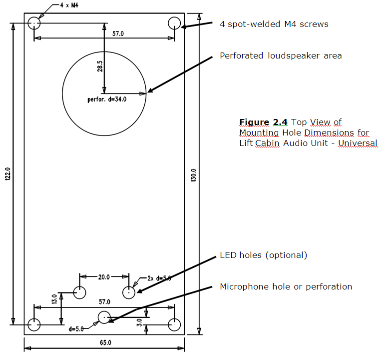 |
To mount the audio unit, you need 4 electrically spot welded M3 or M4 screws, a sufficiently large loudspeaker perforation area and a microphone hole on the inner (back) side of the panel. If needed, you can fix the audio unit on a perfectly degreased surface with a good-quality two-sided foam self-adhesive tape.
Warning
- Leave no gap between the lift control panel and the audio unit surface to avoid acoustic loudspeaker fault and acoustic loudspeaker-microphone feedback.
- Do not use this type of audio unit in a position other than mounted on a sufficiently large board. The acoustic properties of an uninstalled audio unit cannot be guaranteed.
Separate Microphone Mounting
If the microphone is separated (connected by cable) it has a 25×25 mm large board with self-adhesive foil. This helps you mount it easily behind any hole in the panel (the minimum hole diameter is 5 mm, or a group of smaller holes of the same total area). Just glue the microphone directly onto the required place from behind (be sure to degrease and clean the surface carefully before!).
Requirements
- The minimum distance between the loudspeaker and microphone centres is 90 mm. A lower distance may lead to acoustic feedback. A greater distance (within the available 1m cable) does not matter.
- Make sure that the glued-on microphone does not pick up (even partially!) the acoustic pressure from the space behind the panel. Such sensing might result in acoustic feedback since the loudspeaker strongly radiates sound into the cavity.
Separate Loudspeaker Mounting
The loudspeaker is equipped with a cable and can be separated from the electronics by simply sliding it out within the reach of the cables delivered (1m). This option is useful where there is not enough space for the whole electronic equipment. Fit the loudspeaker according to the instructions below:
- While gluing choose such procedures or adhesives that prevent membrane damage by adhesives and volatile substances, or heat.
- We recommend you to keep the loudspeaker sealed to eliminate vibrations.
Frequently Asked Questions Concerning Loudspeaker
- Is it possible to use a common loudspeaker for the communicator and floor announcing machine?
- No, it is not.
- May I use a loudspeaker of my own?
- Yes, but make sure that the impedance is 64 Ω. By doing this you assume responsibility for sufficient volume and frequency range.
- May I place the loudspeaker on the cabin ceiling?
- This placement is not recommended.
- May I use a longer cable with the loudspeaker?
- Yes, but not with the microphone.
Electric Installation
Description of Terminals, Connectors and Jumpers
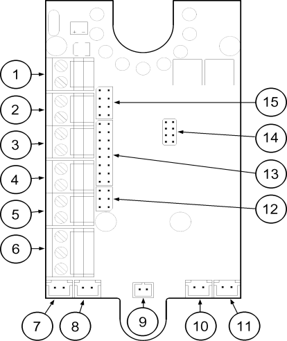 |
Figure: Description of Terminals, Connectors and Jumpers for Lift Cabin Audio Unit – Universal
Terminals | Connectors | ||||
1 | Bus | 7 | “Request accepted” LED | ||
2 | ALARM, voltage activation | 8 | “Connection established” LED | ||
3 | ALARM, contact activation | 9 | Microphone connector | ||
4 | CANCEL, voltage activation | 10 | Loudspeaker connector | ||
5 | CANCEL, contact activation | 11 | Induction loop connector | ||
6 | indicator switches | 14 | Service connector | ||
Configuration jumpers | LED indicators (rear side): | ||||
12 | ALARM / CANCEL inversion | 1. (yellow) | Request accepted | ||
13 | Lift number | 2. (green) | Connection confirmed | ||
15 | Audio unit position | 3. (yellow) | Triphony | ||
| 4. (red) | Upgrade or error | |||
Note
- If external LEDs are connected to connectors 7 and 8, on-board LEDs 1 and 2 will not be shining.
Address Setting
The audio unit address means setting of two jumpers, namely the lift number (1 to 8) and audio unit position (refer to the cover drawing). If you install the audio unit in the cabin of lift 1, you need not change the jumper configuration. In other cases, follow the instructions below:
Instructions
- Release slightly the three screws on the electronics cover.
- Slide the cover to the right to expose the jumpers.
- Set the required changes as shown on the electronics cover.
- Replace the cover and tighten the screws.
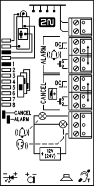 |
Figure: Address Setting for Lift Cabin Audio Unit - Universal
Notes
- Make sure that two audio units do not have an identical address to avoid system error.
- The position-setting jumpers are employed exceptionally, e.g. where a certain audio unit type is used in a position other than normal.
- To recover the initial address setting, follow the drawing on the cover.
Bus Connection
The connection polarity is arbitrary.
Warning
- Connection to different, e.g. higher-voltage, cables leads to damage or destruction of the audio unit.
Caution
- The unit is powered via a 2-wire bus from the central unit. Unplugging of the bus from the CU causes switching off of the unit.
- Avoid the audio unit address duplicity.
ALARM Button Connection
Requirements
The ALARM button design (colour, symbol, button surface, mechanical run) and location have to meet the requirements of the particular installation.
Button control
Requirements
- The ALARM button has to be equipped with a normally open (NO) or normally closed (NC) contact that is not connected with any other circuit.
- None of the ALARM button terminals may be connected electrically with any other electrical circuit and a voltage source other than the NO/NC contact.
- If one of the ALARM contacts is connected to another circuit, appropriate isolation strength according to applicable standards has to be ensured between the contacts.
Instructions
- Leave the ALARM terminal in the LOW position (3).
- With a normally closed contact, leave jumper (12) – right in the default position.
With a normally open contact, switch jumper (12) – right into the HIGH position.
Voltage control
Requirements
- DC 12 to 48V voltage
- The voltage signal has to be active even in the case of power failure.
Instructions
- Switch the ALARM terminal by two pins up into position (2).
- For activation by voltage connection, leave jumper (12) – right in the default position.
- For activation by voltage disconnection, switch jumper (12) – right into the HIGH position.
Caution
- Jumper setting, as printed on the unit cover of pre-production samples, is only valid for CANCEL and wrong for ALARM.
- See above for the proper setting.
Warning
- Ignoring the instructions above may lead to product damage.
CANCEL Input Connection (Door Contact, Optional)
This input helps cancel a rescue request if the lift is fully functional. When the ALARM button is pressed, the system waits for a pre-programmed period of time, which is a little longer than the maximum lift running time. If the lift is functional, it arrives in the required station within this timeout and opens the door. In that case, the rescue request is cancelled. If the door fails to open, the request is accepted.
Find out before installation whether the door opening signal is available in the lift cabin.
Requirements
- In double-door lifts, the signal has to be active only if both the doors open successfully and let the people out.
- The door position signal has to work even in the case of power outage.
Contact control
Requirements
- None of the CANCEL terminals may be connected electrically with any other electrical circuit and a voltage source other than the contact.
Instructions
- Keep the CANCEL terminal in the LOW position (5).
- With a normally open contact, leave jumper (12) – left in the default position.
- With a normally closed contact, switch jumper (12) – left into the LOW position.
Voltage control
Requirements
DC 12 to 48V voltage
Instructions
- Switch the CANCEL terminal by two pins up into position (4).
- For activation by voltage connection, leave jumper (12) – left in the default position.
- For activation by voltage disconnection, switch jumper (12) – left into the LOW position.
Warning
- Ignoring the instructions above may lead to product damage.
Note
- Remember to program delayed calling to make the CANCEL connection work successfully.
Indicator Connection
The basic configuration providing (using an external source) a sufficient illumination intensity of indication elements is shown in the figure:
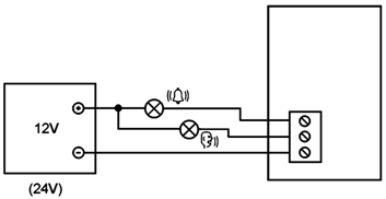 |
Figure: Basic Indicator Connection for Lift Cabin Audio Unit – Universal
Requirements
- The DC power supply has to be backed-up.
Notes
- LN continues working except for the indicators during power outage.
- The indication elements (bulbs, e.g.) may have the maximum current of 200 mA each.
- Mind polarity in this case.
Alternative indicator connection (LED)
Today's LED producing technologies help achieve a relatively good illumination intensity at a low current supply. If a 5 mA LED (with diode loss of approx. 2V) is able to provide efficient illumination in the lift, no power supply is needed. For this configuration see the figure below:
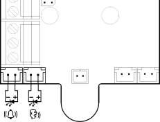 |
Figure: Alternative Indicator Connection for Lift Cabin Audio Unit – Universal
Notes
- The cables required for this configuration are not part of the standard delivery but are available upon agreement.
- In this configuration, the auxiliary indicators on the PCB are not shining.
Induction Loop Connection
The regulations that apply to communicator installations may require a mandatory loop for persons with defective hearing in the lift cabin. In that case, connect the loop to connector (10) with any polarity. The loop including a 1m long cable can be part of your delivery if agreed.
Requirements
- The induction loop has to be placed behind a non-metal, non-magnetic cover in the control panel because the magnetic field of the induction loop cannot go through the metal control panel.
- The induction loop has to be labelled with an appropriate symbol (ear) placed according to applicable standards.