5.2 Introduction to Application
In this subsection, we will show you the application menu layout and basic controls. The application is divided into three menu levels. The first screen upon start includes Configuration / Parameter/ Basic (see the figure below), which displays all of the three menu levels. The horizontal Main menu (Configuration and Logs) helps you select whether to configure the 2N® Lift8 system or supervise the history of logged events. The vertical menus (Parameters, Cameras, IO Modules) help you select the area to be administered. The third menu level, if meaningful, gets displayed horizontally in the right-hand upper corner and includes a list of parameter setting forms.
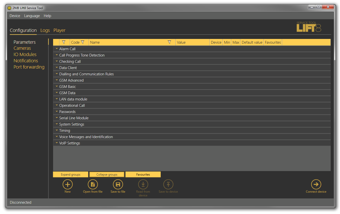 |
2N® Lift8 Service Tool Window
The application main menu consists of three pop-up menus. The Device menu helps you disconnect from/connect to the CU and quit the program. The Setting submenu includes a Statistics window: confirm the request to enable transmission of your system data and software use surveys to help the 2N TELEKOMUNIKACE a.s. company improve the software quality, availability and performance within the applicable law. You can participate in this cooperation voluntarily and cancel your prior approval any time. The Diagnostic package submenu helps you download a package including information relevant for troubleshooting: device state, bus operations and control centre communication. Log in to the CU to get access to this package. Change the language mutation in the Language menu: CZ and EN are available for the time being. Click on Help to find a link to the latest manual and information on the application manufacturer. You will always be warned before logging out or quitting the application in order not to lose unsaved data.
You will be warned against data loss before loading a new configuration and overwriting the current set of parameters. Confirm your intention to avoid unintentional loss of unsaved parameters.
Note
- The language change will not be executed until the application restart.
The Status line displays connection information. From the left: 'Connected to' includes the name of the server to which you are currently connected, 'COM port' specifies your PC COM port if you use a USB cable for connection, 'Current user' displays the currently logged in user, 'FW version' specifies the current CU FW version and 'Serial number' gives the CU serial number.
Upon login to the CU, the Real-time device state keeps displayed to the right in the whole application. Hide and redisplay the window any time with the arrow in its left upper corner (see below). The information is grouped logically: Link properties defines the Link state (idle or calling) and Link type (PSTN, GSM or IP communication level in the CU), GSM network provides information on the GSM / UMTS network to which the SIM card is logged in such as Signal strength in the form of a clear scale and numerical value in dBm, Operator (Provider) name and IP address assigned by the provider's APN server to the SIM card if UMTS / GSM data transmission is allowed and configured. If data flow is disallowed, incorrectly configured or not supported by the SIM, the address will be 0.0.0.0.
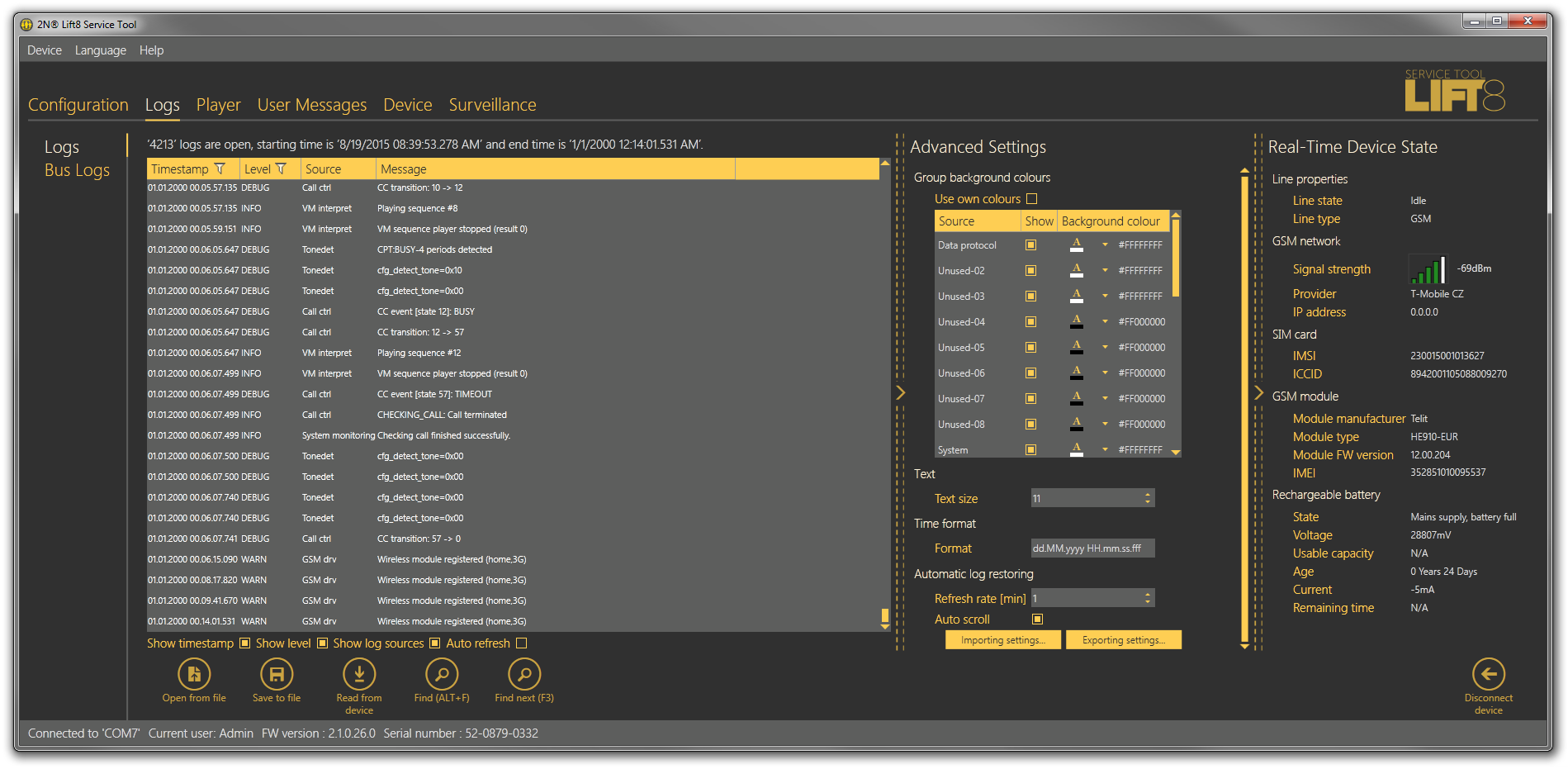 |
Maximum Application Display with Real-Time Device State
The SIM card section specifies the SIM card state and IMSI and ICCID identifiers. The GSM Module section displays the GSM/UMTS module information: Module manufacturer, Module type, Module FW version and IMEI. Battery is devoted to the rechargeable batteries. State simply describes the current state of the batteries: "Mains power, no battery" means that the CU is supplied from the mains, for example. Voltage measures and displays the current battery voltage value in mV. If the value is very low (hundreds of mV), the batteries are disconnected. Usable capacity specifies the battery charging percentage. Age defines the maximum battery life and the age counter has to be reset whenever new batteries are inserted. When the battery life is exhausted, the CU reports an error and the batteries have to be changed. This helps you find out how long your batteries have been used in the device. Current measures the current flow through the batteries: either the charging current when the batteries are being charged or discharging current when the CU is disconnected from the mains and fed from the batteries.
If your CU is equipped with a VoIP module, the Real-time device state section displays the relevant parameters; see the figure below. The section informs you of the line state and type, IP module parameters, IP address or address obtained from the DHC server, network mask, default gateway and DNS server. Finally, like with the GSM / UMTS module, you can see the current battery and charger states. If you use a PSTN module, the line state and battery charging state will only be displayed.
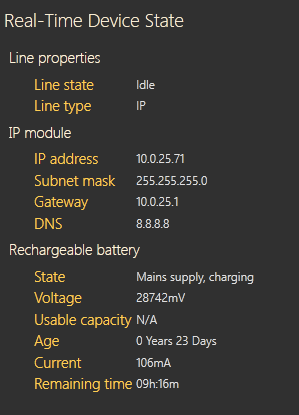 |
Real-Time Device State for VoIP Module
Caution
- The Real-time device state only displays the Link properties and Battery. The other parts are displayed automatically depending on the HW connected.
The lower part of the application includes the Logout button (to the right) and other important controls, which may be different in different menus. The table below describes all the buttons available in the application.
Basic Controls
| New helps you create a new table of parameters. The existing table will be replaced after a warning. | |
| Open from file helps you read the table of parameters from a disk file. | |
| Save to file helps you save the current table of parameters into a disk file. | |
| Connect device switches the user into the 'Connect to device' menu. | |
| New group helps you create a new CU connection group in the Connect to device screen. | |
| New server helps you create a new CU connection in the Connect to device screen. | |
| Delete selected deletes the currently selected objects from the list in the Connect to device screen. | |
| Back is only available in the Connect to device menu and helps you return to the Configuration / Parameters menu if you do not want to get connected to any CU. | |
| Connect logs in the user to the configured CU. | |
| Connect to server connects the user to 2N® Lift8 Server and displays the list of set and active Central Units to be connected to. Connect is always used for CU connection. | |
| Connect to another lift disconnects the user from the current intercom and displays the list of connected 2N® Lift8 Server devices. | |
| Disconnect server disconnects the user from the server and displays the Connect to device screen. | |
| Disconnect device logs out the currently logged-in user from the CU. | |
| Find helps you activate log searching. The Find window is displayed for you to set a string (word) to be found. | |
| Find next helps you find another occurrence of the set string (word). | |
| Read from device downloads the current settings and logs from the CU. | |
| Save to device helps you save new parameters into the CU memory. | |
| Get new image helps you download a preview from the camera connected to the selected camera module. | |
| Rotation to left turns the image left by 90°. | |
| Rotation to right turns the image right by 90°. | |
| Add action adds a new IO module action. | |
| Delete action deletes the selected action. | |
| Click Verify to verify the validity of the LUA script for IO module control before loading to the CU. | |
| Click Save script to save the current script into a file for backup and later use if necessary. | |
| Click Load script to load a script from the backup file and delete the original script. | |
| Click Open directory to load video files from a disk/SD card.
| |
| New set helps you create a new set of user voice messages. | |
| From device helps you download user messages from the CU. | |
| To device helps you upload new user messages into the CU memory. | |
| Load from directory helps you load the list of user messages from a directory to a disk. | |
| Save to directory saves the list of user messages into a selected folder onto a disk. | |
| Print HW setup – diagram helps you print out the current 2N® Lift8 HW settings as an image. | |
| Print HW setup – text helps you print out the current 2N® Lift8 HW settings as a text. | |
| Upgrade starts FW uploading to the CU. | |
| Refresh updates the list of connected communicators and the CU bus. | |
| Zoom in helps you get a close-up view of the diagram displayed. | |
| Zoom out helps you see more of the diagram displayed at a reduced size. | |
| Delete all in device erases all user-recorded messages from a set. After all the parameters are saved, the messages will be deleted from the CU too. | |
| Open from file and save to device opens a file viewer for you to select the licence file for your CU. This file will be downloaded to the CU upon confirmation. | |
| Start watching connected units activates the function like the Reset button on the CU. It makes the system check the audio units (cabin, fireman only) for proper connection and function. Refer to Subs. 4.8 for details. | |
| End watching units deactivates the unit watching function. |