2.16 LAN Module
Description
The main purpose of the LAN module is to connect the ETH supporting lift controller. Like the serial module, it can support the Internet connection via the Central Unit WAN interface. Here the VoIP or GSM/UMTS module can be mounted. In general, it is an interface providing connection to a network. Set the LAN module address as the default gateway on the devices connected. Then you can get connected to the Internet via the Central Unit. Set the LAN module parameters, such as IP address and subnet mask, using the Service Tool in the LAN Data module section (parameters 1500 and 1501). Port forwarding is closely associated with the Data module and ensures that communication directed to a certain WAN port is forwarded to the selected port and IP address in the LAN Data module network.
 |
Before You Start
Product Completeness Check
Check whether the product package is complete before installation.
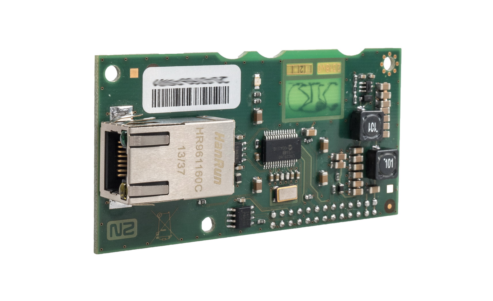
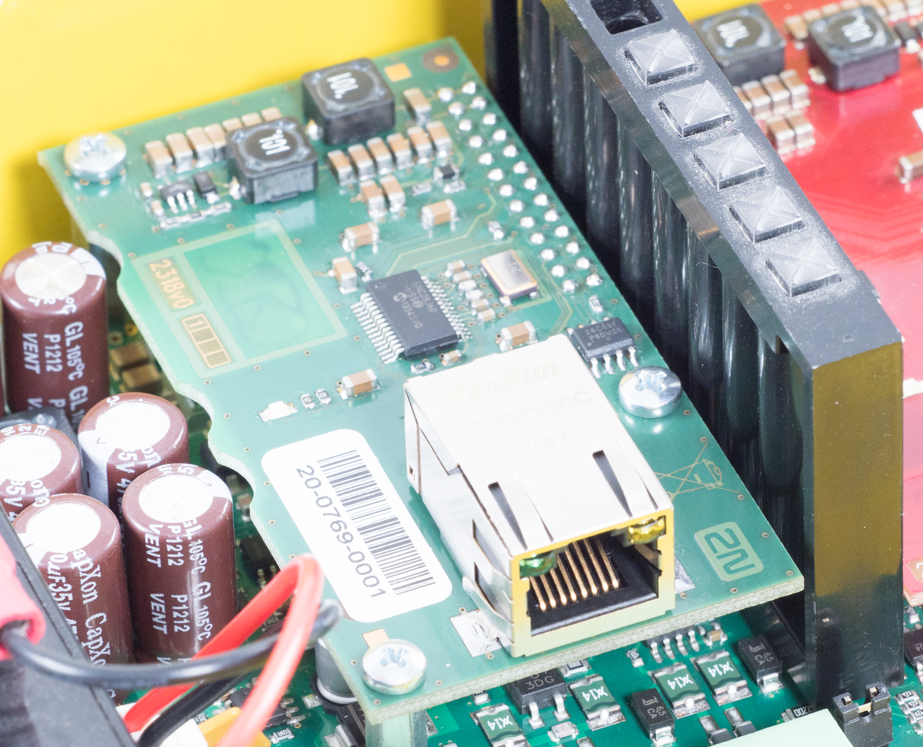
The LAN module package contains:
- 1 electronics board (Ethernet level)
- 2 long threaded spacers
- 1 short screwed spacer
- 1 screw
Description of Connection
- Disconnect the CU from the mains supply.
- Loosen the three screws on the upper cover of the CU.
- Move the CU upper cover in such a way that you can remove it.
- While removing the cover, proceed with caution - be careful about the earth wire connecting the cover with the CU bottom part. Do not disconnect the wire unless there is a reason to do so!
- Disconnect the back-up rechargeable batteries if connected (using the FASTON cable end pieces connecting the rechargeable batteries with the motherboard).
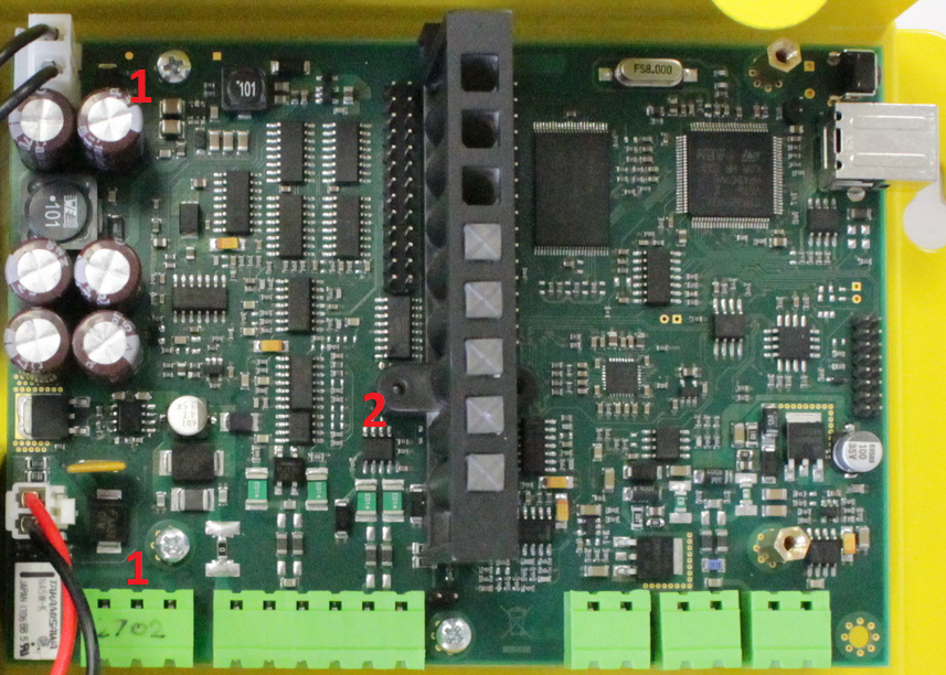
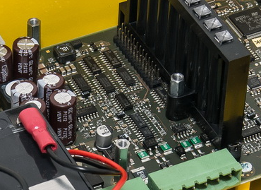
Unscrew 2 screws (1) and replace them with 2 threaded spacers. Fit the screwed spacer (2) into the LED plastic cover (see Fig.).
Tip
To make your spacer mounting easier, turn the screw until it stops and use a cross-point screwdriver to fit the spacer. Having tightened the spacer in the LED plastic cover, use flat-nose pliers to secure the spacer against spinning and remove the screw.
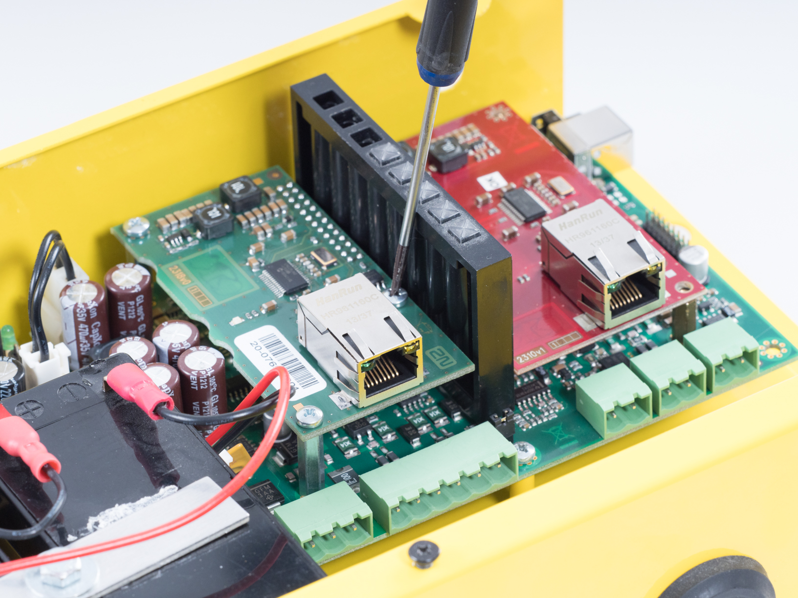
- Now mount the Ethernet level. Be careful while putting the module on the pins. Make sure that you have connected all the pins to the module connector.
Having fitted the pins into the connector correctly, you can fix the module using 3 screws (see Fig.).
- Now connect the Ethernet cable via RJ-45.
- Replace the rechargeable batteries and CU cover and tighten the 3 screws to fit the cover.
- Reconnect the CU to the mains supply.