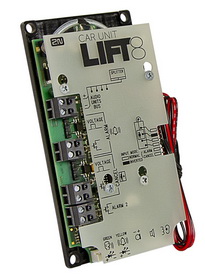
2.11.1 Fireman PCB
Description: 1-Button Version
The Fireman audio unit improves the fire fighting operations by setting up top priority calls between the Fireman audio unit and the cabin and machine room audio units in one and the same lift shaft. If any of the machine room audio units is configured as the control centre (intercom), you can join in the Fireman call.
 |
Install the Fireman audio unit in a dedicated space that can be easily accessed by firemen.
The Fireman call has the highest priority, suspending all the other calls (refer to Function Description). It is connected with the cabin audio unit in one and the same shaft.
Press the button to set up the call. The call duration is infinite. Repress the button to stop the call.
The Fireman call setup is signalled by the Fireman audio unit LED (mounted on the PCB or carried externally from connector 8).
If the control-centre configured machine room audio unit is used, the Fireman call is signalled by a green LED flashing on the audio unit. Push ![]() (for longer than 2 s) on the audio unit keypad to join in the call. Push
(for longer than 2 s) on the audio unit keypad to join in the call. Push ![]() (for longer than 2 s) on the audio unit keypad to leave the call without terminating it.
(for longer than 2 s) on the audio unit keypad to leave the call without terminating it.
Caution
- The Fireman calls has the highest priority and suspends all the other calls except for the Fireman call set up in another shaft.
- The Fireman call is set up by the cabin audio unit in one and the same shaft.
- You can join in the Fireman call from a machine room audio unit configured as the intercom.
Button is not included.
Description: Knob+Button Version (Push-To-Talk)
The Fireman audio unit improves the fire fighting operations by setting up top priority calls between the Fireman audio unit and the cabin and machine room audio units in one and the same lift shaft. If any of the machine room audio units is configured as the control centre (intercom), you can join in the Fireman call.
|
Install the Fireman audio unit in a dedicated space that can be easily accessed by firemen.
The Fireman call has the highest priority, suspending all the other calls (refer to Function Description).
Press the detent button switch or turn the knob (0 > 1) to set up the Fireman call. The call duration is infinite. Repress the button or return the knob to stop the call. (The detent button switch or knob is connected to terminal 3).
The Fireman call setup is signalled by the Fireman audio unit LED (mounted on the electronics board or carried externally from connector 8). Push the button switch (Push to talk) to activate the audio unit microphone and speak to the other audio units (the LED starts flashing). While the button is pushed, no sound is transmitted from the other audio units. Release the button to allow the persons at the other audio units (cabin, machine room or machine room as intercom) to talk.
If the control-room (intercom) configured machine room audio unit is used, the Fireman call is signalled by a green LED flashing on the audio unit. Push ![]() (for longer than 2s) on the audio unit keypad (green LED shining) to join in the call. Push
(for longer than 2s) on the audio unit keypad (green LED shining) to join in the call. Push ![]() (for longer than 2 s) on the audio unit keypad (green LED flashing) to leave the call without terminating it.
(for longer than 2 s) on the audio unit keypad (green LED flashing) to leave the call without terminating it.
Caution
- The Fireman calls has the highest priority and suspends all the other calls except for the Fireman call set up in another shaft.
- The Fireman call is set up to the cabin and machine audio units in one and the same shaft.
- You can join in the Fireman call from a machine room audio unit configured as the intercom.
Button is not included.
Before You Start
Installation Conditions
- Make sure that the panel is ready for installation, check the speaker perforation area.
- Make sure that there is 65×130×20 mm of free space behind the panel.
Product Completeness Check
Please check the product package for completeness before starting installation.
- Cabin audio unit package contents:
- 5 straps
- 1 electronics board
- 3 board-slid terminals, see the photo
- 1 board-mounted jumper (defining the button version)
- 1 mounting panel
- 1 speaker (directly or cable connected)
- 1 microphone (directly or cable connected)
- 1 printed cover
Mounting
Electronic Installation
This audio unit is designed for mounting behind the lift control panel. Prepare the panel for installation as shown below:
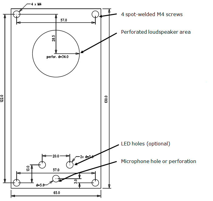 |
Figure: Cabin Audio Unit – Universal Mounting Hole Dimensions
To mount the unit, you need 4 electrically spot-welded (from the inner panel side) M3 or M4 screws, a sufficiently perforated speaker area and a microphone hole. If needed, a high-quality double-sided foam self-adhesive tape can be used for installation on a perfectly degreased surface.
Warning
- Leave no gap between the lift control panel and the audio unit surface to avoid acoustic speaker fault and acoustic speaker-microphone feedback.
- Do not use this type of audio unit otherwise than mounted on a sufficiently large board. The acoustic properties of an uninstalled audio unit cannot be guaranteed.
Separate Microphone Mounting
If the microphone is supplied separately on a 25 x 25 mm large board with self-adhesive foil and with a cable, you can mount it easily behind any hole in the panel (keep the minimum hole diameter of 5 mm or a group of smaller holes of the same total area). Just glue the microphone directly onto the required place from behind (be sure to degrease and clean the surface carefully before mounting!).
Requirements
- The minimum distance between the speaker and microphone centres is 90 mm. A lower distance may lead to acoustic feedback. A greater distance (within the available 1m cable) does not matter.
- Make sure that the glued-on microphone does not pick up (even partially!) the acoustic pressure from the space behind the panel. Such sensing might result in acoustic feedback since the speaker strongly radiates sound into the cavity
Separate Speaker Mounting
The speaker is equipped with a cable and can be separated from the electronics by simply being slid out within the reach of the cables delivered (1 m). This option is useful where there is not enough space for the whole electronic equipment. Fit the loudspeaker according to the instructions below:
- While gluing choose such procedures or adhesives that prevent membrane damage by adhesives and volatile substances, or heat.
- We recommend you to keep the speaker sealed to eliminate vibrations and ensure electric insulation.
Frequently Asked Questions Concerning Speaker
- Can I use a speaker of my own?
Yes, but keep the impedance of 64 Ω. Doing this, however, you assume responsibility for sufficient volume and frequency range.
- Can I use a longer cable for the speaker?
You can use a longer cable for the speaker, but not for the microphone.
Electric Installation
Description of Terminals, Connectors and Jumpers
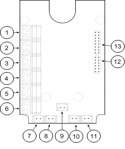 |
Figure: Terminals, Connectors and Jumpers on Cabin Audio Unit – Universal Board
Terminals | Connectors | |||||||||
|---|---|---|---|---|---|---|---|---|---|---|
1 | Audio unit bus | 7 | Unconnected | |||||||
2 | Unconnected | 8 | LED | |||||||
3 | Unconnected (1-button version) Fireman call activation – with detent (2-button version) | 9 | Microphone connector (optional) | |||||||
4 | Unconnected | 10 | Induction loop connector | |||||||
5 | Activation/Deactivation – without detent (1-button version) Push to talk – without detent (2-button version) | 11 | Speaker connector | |||||||
6 | Unconnected | 13 | Servicing connector | |||||||
Configuration Jumpers | Two LED Indicators (from the other side) | |||||||||
12 |
The lower pin defines the button count
| 1. (yellow) | Shining – active Fireman call Flashing – Push to talk (for 2-button versions only) | |||||||
2. (green) | ||||||||||
Note
- If an external LED is connected to connector 8, the LED 1 indicator will not be shining.
Bus Connection
Pull the terminal out of connector 1 – Audio units bus, connect the bus audio units wires and replace the terminal to connector 1. Mind the polarity.
Warning
- The audio unit is intended for 2N® Lift8 audio unit bus connection exclusively. Do not connect it to other wires to avoid its damage or destruction.
- Maintain polarity while connecting the audio unit to avoid audio unit error.
Caution
- The audio unit is powered via a 2-wire bus. Disconnection of these wires results in the audio unit switch-off.
- Proper polarity (+ -) is shown on the cover of audio unit.
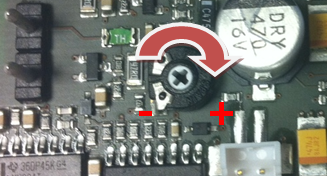
Volume Setting
Loosen the four screws slightly and move the cover downwards. Remove the cover. Use the trimmer in the lower part of the electronics to adjust the volume (see the figure below).
 |
Caution
- Use the trimmer to set the best acoustic properties while eliminating feedback.