3.3 Use
Configuration
Upon login, you get to the Configuration main menu where you can find almost all the 2N® Lift8 settings. The user may access the menus allowed by its role. The Administrator can administer the whole system without limitations: divide users into groups, assign the user roles, assign the users intercoms to be configured and monitored, set the Call server for intercom checking calls and configure the storages for buildings plans. The Surveillance menu provides a view of all the configured lifts on the world map including their current states. Now let us explain what the menus are used for.
Application Language Change
The currently used language abbreviation is shown on a grey bar in the application upper corner. Put the mouse cursor on the abbreviation to open the menu of all supported languages. Before changing the language decide whether to apply the change immediately making the application restart automatically and having to relog in, or apply the change after quitting the application and relogging in.
Intercoms
The Intercoms menu includes a database of the intercoms defined on the server. The intercom list to the left includes all the available intercoms. Click Group by to arrange the intercoms according to the contact number, database ID or type of authorisation (Authorised, Unauthorised and Unknown). Or, you can arrange the intercoms according to their functions. Click Intercoms to display either all the intercoms or just functional/non-functional intercoms. You can use the search function to find the required intercom: enter the intercom name (or a sequence of characters) into the search row. The function requires no confirmation and starts searching the database the moment you enter the first character. Add more characters to refine the filter until you find the required intercom.
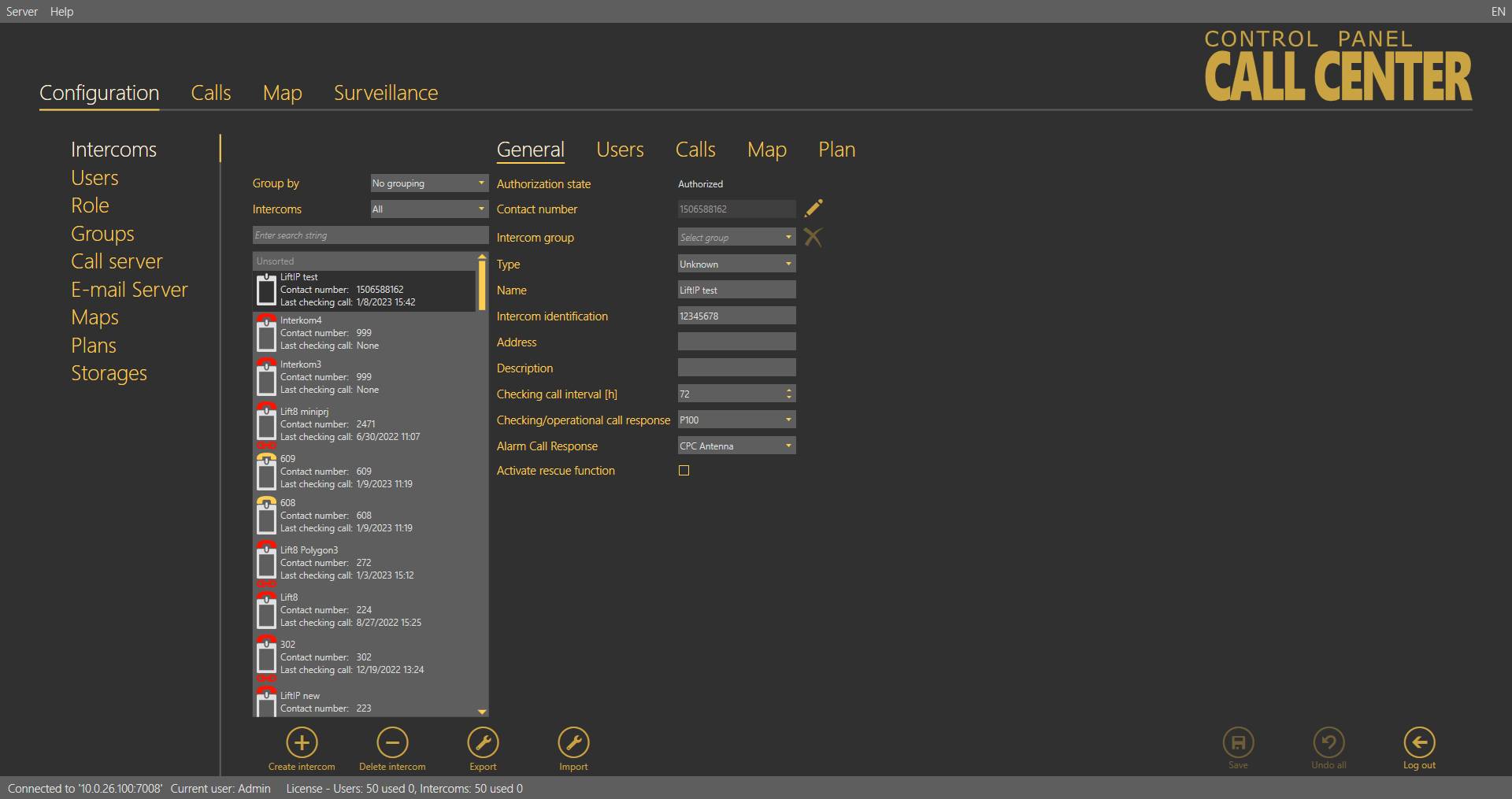 |
Intercoms Menu
The list in the figure above includes some information on the intercom. The icon at each intercom indicates the lift cabin and can have several functions and meanings, which can be combined (see the table below).
| A red handset above the icon indicates that the intercom failed to make a checking call within the timeout and is thus marked as non-functional. When the intercom makes a correct checking call, this state will disappear. |
| A yellow handset above the icon signals that the intercom made a checking call within the timeout but the first call was not accepted OK. This happens when the first call was terminated for some reason, but the following calls were OK. When the intercom makes correct checking calls within the checking call timeout, this state will disappear. |
| A yellow question mark signals an intercom that was created by a checking call but has not been confirmed by Administrator yet as a real intercom. Refer to the Intercom Creation subsection below for details. |
| This symbols a functional intercom: 2N® SingleTalk, 2N® LiftNet, 2N® Helios or Unknown, probably supplied by another manufacturer and able to communicate with the 2N® Call Center – Server via CPC / P100. |
| A functional 2N® Lift8 intercom. The red chain below the icon indicates the Disconnected state between the 2N® Server and the Central Unit. |
| A functional 2N® Lift8 intercom. The blue chain below the icon indicates the Connection established state between the 2N® Server and the Central Unit. |
| A functional 2N® Lift8 intercom. The green chain below the icon indicates the File transmission state between the 2N® Server and the Central Unit. |


Tip
- The 2N® Call Center – Server is able to work with the third party equipment via the standard communication protocols (CPC and P100) instead of proprietary protocols. Set the type to Unknown to communicate with such equipment.
Intercom Creation
Add an intercom to the database as follows:
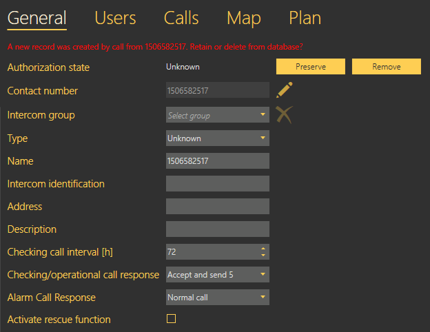
The first way is to install a CU and configure it to call the number that the server uses for checking calls. When the CU makes the first checking call to the server, a new intercom card is created and basic information on the intercom is included: the telephone number used for the checking call is filled in as the Name. The so-created intercom is marked as unauthorised to eliminate unintentional calls (telemarketing, e.g.). To authorise this intercom, use the Basic tab for this intercom in the 2N® Control Panel, which informs you that a new record has been created by a call from number x and asks you whether you want to keep it in the database or delete it. Press Preserve to add the intercom to the database or Remove to delete the intercom from the database if unintentional (telemarketing, error).
 |
Intercom Authorisation by Checking Call
Complete more intercom card parameters for authorisation. See below for details (Intercoms).
Note
- If the device that is making the checking call for the first time supports the CPC or P100 protocol, you have to set this parameter manually. Calls from a number that is not included in the database are always served by the server by sending DTMF 5 and hang-up. If you want to use the above-mentioned protocols for checking and alarm calls, set them manually.
The other intercom adding method is to create an intercom card in the database. Click on Create intercom card to open a window in which you can set the contact number for intercoms with one and the same phone number. Click on the combo box to add another intercom to a contact number included in the database.
Note
- Multiple intercom functionality under one contact number is important where intercoms are connected to a gateway or PBX which identifies itself as a single external number.
- If you assign multiple intercoms to one number, the evaluation logic will change depending on the checking call response type:
- With confirmation 1 and 5, Receive and send 5 – the incoming checking calls are counted. The system waits until the preset count of intercoms have called and then designates the whole set of intercoms under the given number as functional. If, however, one of the intercoms fails to call within the timeout, all the intercoms will be regarded as non-functional.
- CPC, P100 – identification must be set for each intercom under the given number. Each call is evaluated separately. If the number and Id match, the intercom is marked as functional.
Caution
- If the CPC or P100 protocol is set to multiple intercoms with one and the same number, complete the correct identification for each intercom. If the Id is wrong, the system will not evaluate the checking calls correctly.
Confirm the number dialling to get into the General menu. Complete and save all necessary data as described in the Intercoms subsection below. As this intercom has not made a checking call yet, it will be considered non-functional. Install it and make the first checking call to make the intercom ready for use.
Caution
- The intercom that fails to make a checking call within the timeout will be marked as non-functional and remain so until the next correct checking call. A non-functional intercom is visible to the technician for check.
Tip
- Name and Telephone number are mandatory parameters for a new intercom. Complete these values to validate and save the intercom card. No more parameters are necessary for the function. However, you are strongly advised to complete the whole intercom card correctly to facilitate intercom search and dispatchers' and rescuers' work.
Each created intercom is added to the end of the table. Select an intercom for editing and configuration. You can use multiselect to change (delete, export) parameters for a higher number of intercoms: either hold Ctrl to select the objects or hold Shift to select the first and last objects thus selecting all the objects between them. All the changes or exports made over the selected intercoms will apply to all of them.
Intercoms
Select an intercom to open an extensive menu level with intercom identification forms, checking call evaluations, maps and local plans of the building where the intercom is installed. Let us describe each of the forms.
General
The General form helps you configure general parameters for an intercom. The first row defines the Authorisation state of the selected intercom. All the intercoms added manually to the database or created automatically and confirmed as real intercoms are authorised. Contact number provides the CU identification. 2N® Lift8 makes checking calls from this number and 2N® Call Center – Server makes active checking calls to this number: enter either a SIM card in the CU, number of the PSTN line to the intercom or number of the PBX/gateway behind which the intercom is located. Intercom group specifies the group to which the intercom is assigned. Select an item from the list to change the group. Press the cross symbol to remove an intercom from all the groups.
Type defines the type of device: 2N® LiftNet, 2N® SingleTalk, 2N® Lift8, 2N® Lift1, 2N® LiftIP or Unknown. Refer to the Intercom Creation subsection above for details. Name defines the intercom name. Set a name equal to the contact number for an automatically created intercom. Intercom identification is primarily used by the CPC a P100 protocols for counterparty authorisation. As identification is not set automatically during creation, complete the value to make the two protocols work properly. In the case of checking call rejection/confirmation with a DTMF character, this parameter is not checked off. Enter the address of the building in which the intercom is located into the Address field to display this information on the map used by Technician for repairs or Dispatcher for rescue team navigation. Fill in brief information on the intercom to be installed in the Description item: location, purpose, specific settings and so on.
 |
Intercoms – General Menu
The Checking call period specifies the timeout within which the intercom must call the 2N® Call Center – Server or after which 2N® Call Center – Server makes active checking calls. The intercom can call the 2N® Call Center – Server any time within this timeout, but having exceeded this value, it will be marked as defective. The non-functional status will be removed when another checking / alarm call arrives in the server from this intercom. The default value of this parameter is 72 hours. The Alarm call response specifies the type of alarm call processing: Normal call, Confirm with 1, CPC Antenna, CPC KONE and P100. Similarly, the Checking call response specifies the type of checking call processing: Reject, Accept and send 5, Confirm with 1 and 5, CPC Antenna, CPC Antenna 2N Ext, CPC KONE and P100. Complete the serial number of your intercom in the Serial number field. Together with Password, this parameter is relevant for a correct function of the data tunnel. The default password is 2n. Click Save to confirm the setting. If you select the 2N® Intercoms type, set the outgoing checking call parameters too: select Active checking calls to enable active checking calls for the selected intercom, complete First run to define the first checking call and Next run to define the next checking call to the intercom. Complete the Unsuccessful call repeat count to specify how many checking call attempts are to be made before the system detects an error and executes the action set in the Call server. If the lift is equipped with a camera, enable loading images from the camera using a checkbox. This will be applied to incoming calls in the 2N® Call Center – Communicator.
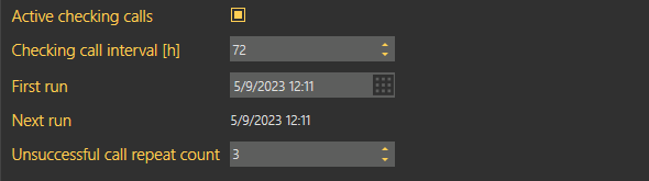 |
Extended Active Checking Call Settings
Where the lift is equipped with a camera, tick off the Download camera image option. This becomes active in the incoming call in the 2N® Lift8 Communicator. Enable the rescue mode monitoring with the Activate rescue function checkbox. In case an alarm call is received from the intercom, the error message announcing that the rescue action is in progress will be displayed and transferred into the 2N® Lift8 Communicator. You can terminate this caution manually or by pressing the End rescue process button, or the rescue process will be terminated automatically after the incoming operational call has been evaluated.
Note
There are two types of checking calls in 2N Helios.
- Standard checking call, which waits until the intercom calls and then evaluates the call interval.
- Active checking call, in which the server itself dials the intercom as scheduled and evaluates the intercom response (pick-up/reject/no answer). For this purpose, the first Call server line is always used as it is assigned extended error call notification settings.
The active and standard checking calls can work on a single server and the use of one type does not exclude the use of the other in any way.
The list of intercom error states is displayed below the parameter list whenever a failure occurs. These states are only displayed for the intercoms that support sending of these states. Information is transmitted to the server via operational calls and CPC and P100 protocols. Like the rescue mode, these states can be ended using the application button or automatically by an operational call.
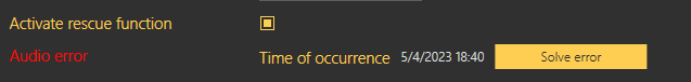 |
Error State Display
The following device states are monitored with the aid of operational calls.
| State | Error |
|---|---|
| Battery failure | Sent if the battery capacity falls below a defined limit or the batteries are older than 2 years. |
| Stuck button | Sent whenever the Alarm button gets jammed due to a mechanical defect or sabotage. |
| Audio error | Sent whenever the audio unit audio test fails. |
| Rescue end | Enabled automatically whenever an alarm call comes in. |
If the server data tunnel is supported, you can download the current device state from the server. Once the tunnel connection has been established, click Connect to set up an active connection via the tunnel and view the current device state like in the 2N® Lift8 ServiceTool. Click Disconnect to quit the device state monitoring mode.
Caution
- Data is transmitted between the intercom and server continuously while the connection is active. If the device is located in a limited traffic network (mobile data, e.g.), data transmission fees can be charged.
Users
The Users menu provides a list of all users with the right to view/administer the selected intercom. Administrator may administer all the system intercoms, users and roles regardless of group assignment. The list of Assigned users displays all the users authorised for the selected intercom. To add a user, select the user in the Not assigned users and move it to the Assigned users with the arrow. To delete a user, select the user in the Assigned users and move it to the Not assigned users with the arrow key. To search a user, enter the string to be searched into the field above the list and see the filtration result in the associated list immediately. Click Save to save the new settings.
Caution
- Users cannot be moved to/from groups if this would lead to the exceeding of the user license limits.
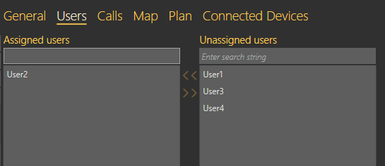 |
Intercoms – Users Menu
Calls
Find the list of active calls related to the given intercom in the Calls menu. There are three pop-up menus for checking, alarm and operational calls respectively. See below for details.
Checking Calls
The Checking Calls table includes a list of all checking calls that have been received by the 2N® Call Center – Server since the intercom addition. Click the filter button at each column to use filtration for call history search. Refer to the Calls subsection for details. The table provides the following information: checking call Timestamp, CU Contact number, Intercom identification if CPC/P100 was successfully used and checking call Result string. See the figure below.
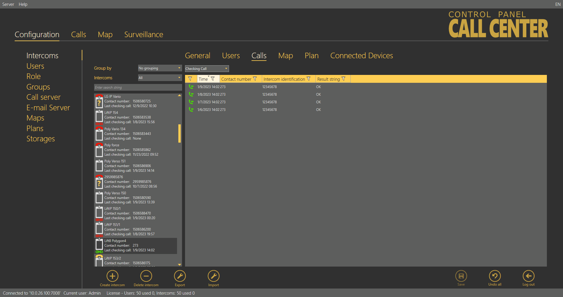 |
| Intercoms – Calls – Checking Calls Menu |
Alarm Calls
The Alarm Calls table includes a list of all alarm calls that have been received by the 2N® Call Center – Server since the intercom addition. Click the filter button at each column to use filtration for call history search. Refer to the Calls subsection for details. The table provides the following information: alarm call Timestamp, CU Contact number, Shaft number, Audio unit position, Intercom identification if CPC/P100 was successfully used and call-processing Agent name. The last column Note shows the note entered by the dispatcher during the alarm call.
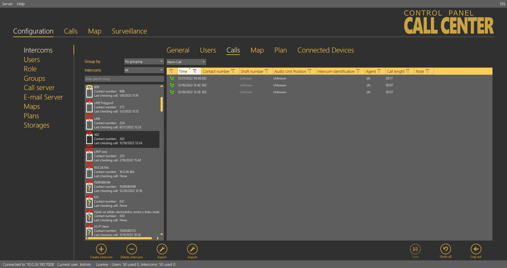 |
Intercoms –Calls – Alarm Calls Menu
Operational Calls
The Operational Calls table includes a list of all operational calls. The operational call is initiated by an action in the Central Unit, which calls the server and transfers the device state information via the CPC/P100 protocol. As a rule, the action transits into an error state and then, if everything is OK, to the OK state. The most recent actions are marked green or red in the table. It is because error messages (stuck button, e.g.) are marked red until the OK state message is received. Once received, the OK state remains green and the other states turn grey to indicate that the error situation has been solved successfully.
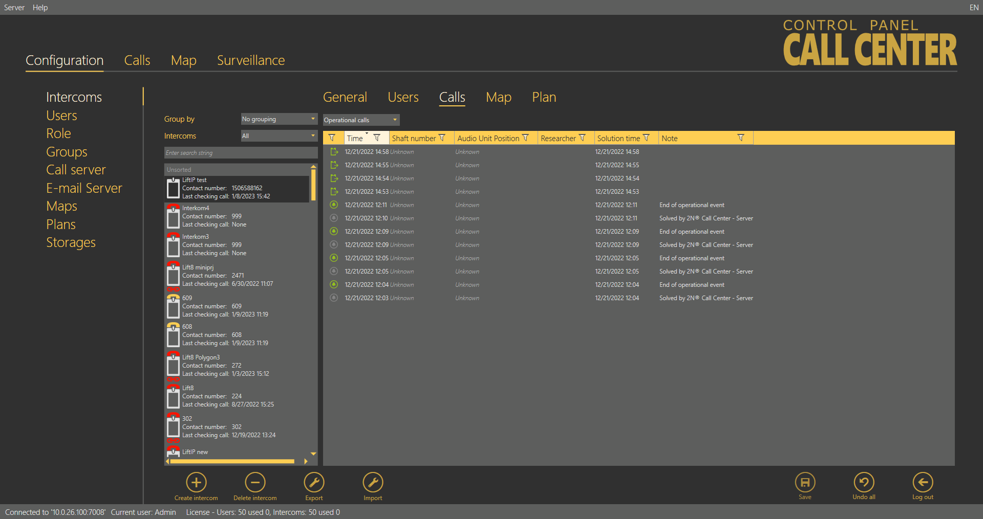 |
Intercoms – Calls – Operational Calls Menu
Map
If you filled in the intercom address in the General menu, the Map menu will display the intercom map position. Use the slider in the left-hand upper corner to zoom in and out. Find the current zoom value above the slider. The intercom address is displayed below the map. If the address is incorrect, change it here. The change will appear in the General menu too. Click Check address to set a new address and press Save to add the address to the database. Activate the map display including the intercom position in 2N® Call Center – Communicator by selecting the function checkbox.
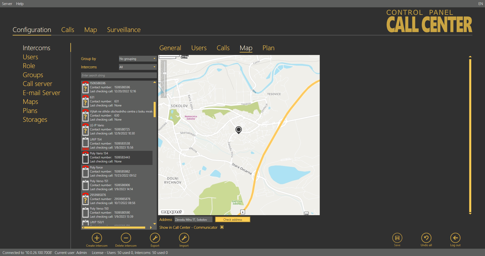 |
Intercoms – Map Menu
Plan
If you have set a storage, added a plan and set the plan in the General menu, the plan will appear in the Local Plan menu. Use the sliders to find the intercom location and move the intercom onto the map with the left button. See the intercom default position in the new plan in the left-hand upper corner. The plan also displays other intercoms in the building including colour states: orange indicates the intercom that is being configured, green means another functional intercom and red denotes a defective intercom that failed to make a checking call within the timeout. A phone number is displayed for each intercom too. Select an option in the Available plans to change the intercom plan. Click Save to confirm the settings. Activate the plan display including the intercom position in 2N® Call Center – Communicator by selecting the function checkbox. Use Remove plan to remove a selected intercom plan.
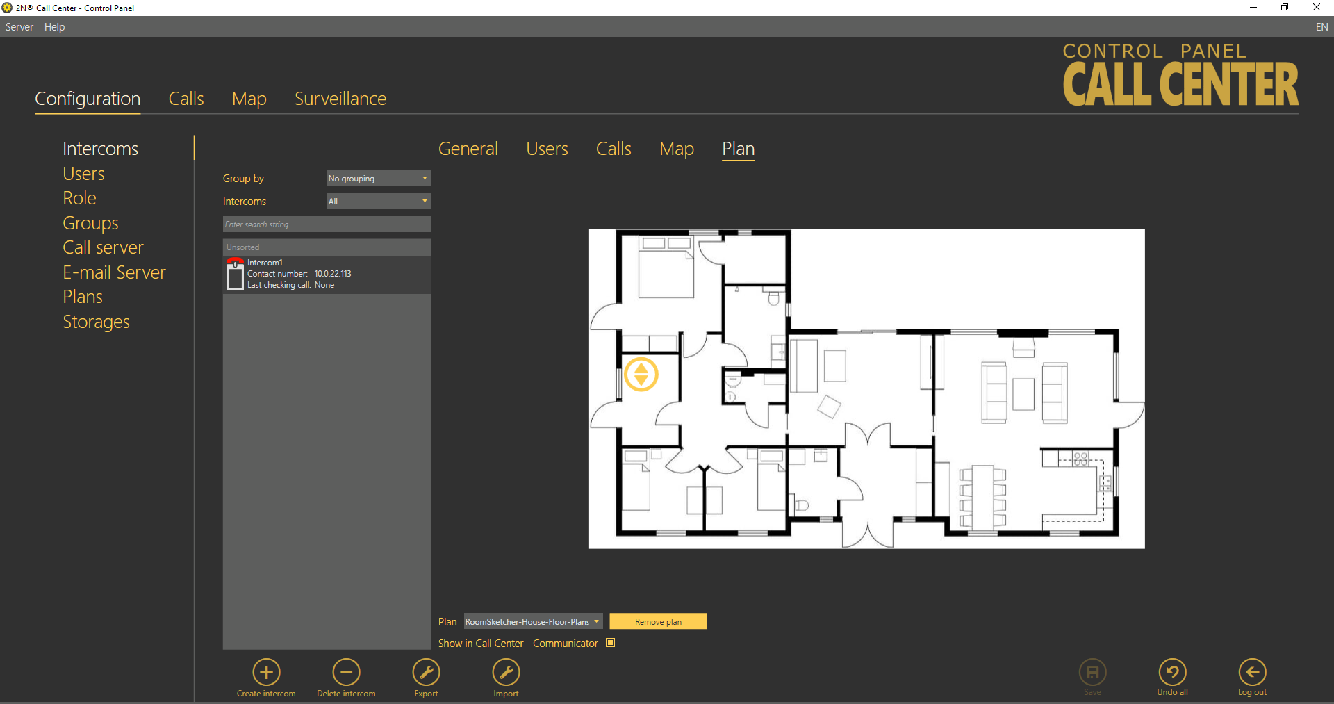 |
Intercoms – Local Plan Menu
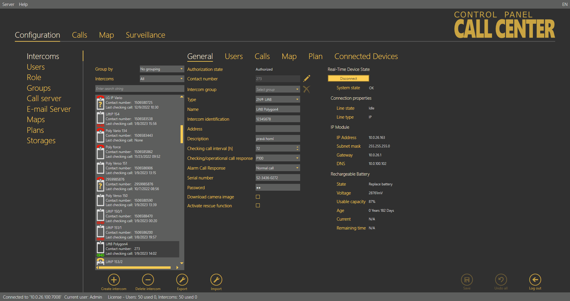
Connected Devices
The Connected Devices menu is another part of the intercom monitoring service. The menu is displayed only if the intercom type is set to 2N® Lift8. The other types do not support device monitoring. If the Central Unit - server connection is active, press Get a scheme of connected devices to create a tunnel for the ControlPanel application to download the diagram of the devices currently connected to the CU and save it onto the PC disk. The connection remains active and the device diagram can be updated any time. At the same time, the current device state is activated on the General tab. Click Log out to close the tunnel connection. The last-downloaded diagram is then saved and displayed any time later in the application. The diagram of connected devices is similar to that in the ServiceTool application. Press the respective buttons in the lower part to print out the diagram as a text or image, or zoom in/out the view. Use the checkboxes to display extended information on the devices connected.
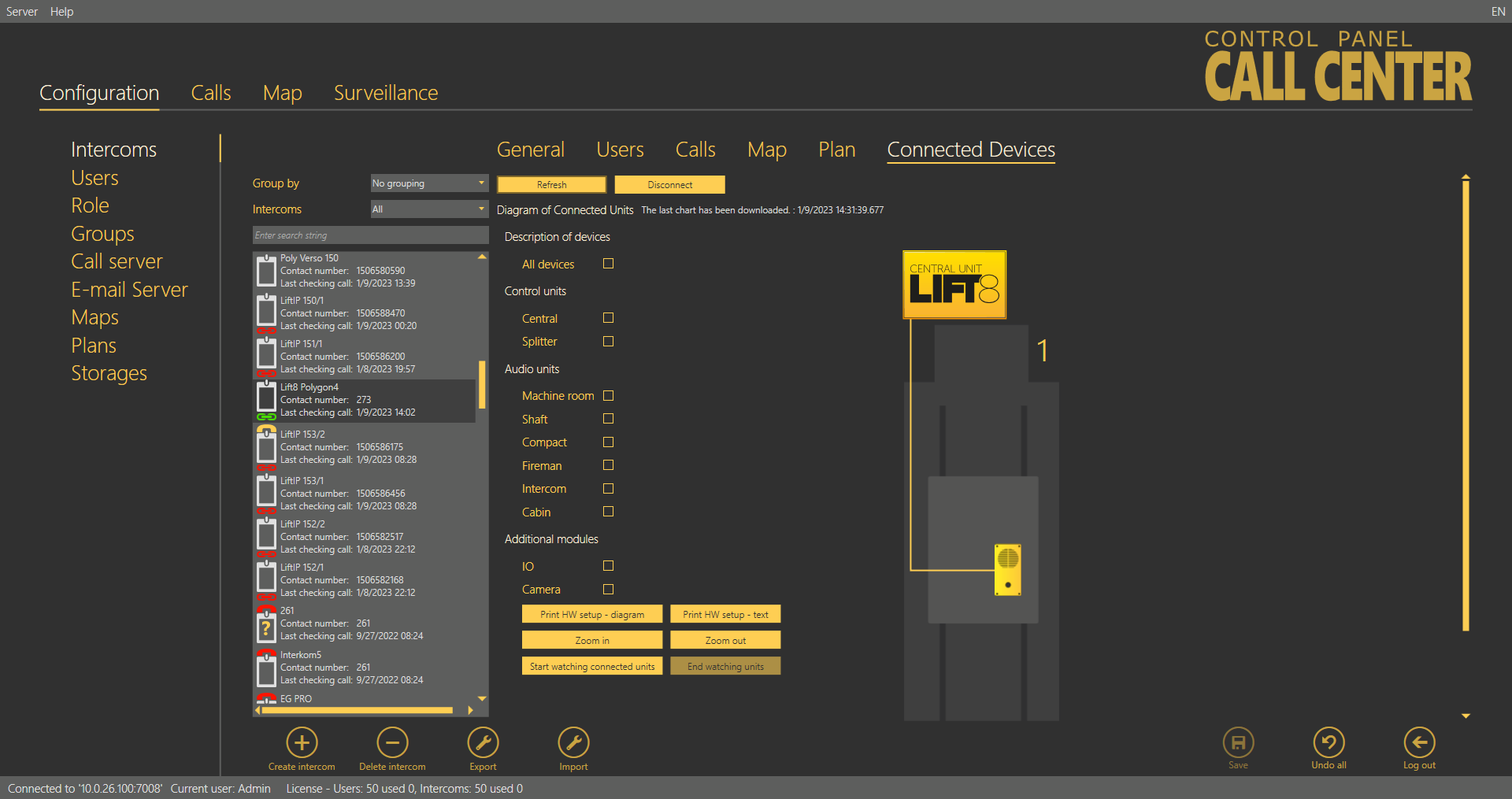 |
Intercoms – Connected Devices
The unit watching buttons help you enable/disable the function. The system behaves like with the Reset button. All the units to be watched are green-highlighted and an error is detected and displayed if there is a loss of connection.
Caution
- Data is transmitted between the intercom and server continuously while the connection is active. If the device is located in a limited traffic network (mobile data, e.g.), data transmission fees can be charged.
- The diagram downloads are saved on a working station with the ControlPanel application running instead of the server. Having logged in from another PC, you cannot see the diagram and have to download a diagram of your own.
Export
The table export function is available in the Intercoms – Users – Calls menu. To enable the function, click Export or use the context menu displayed with the right mouse button above the selected object or objects if multiselect is used in the Intercoms – Users menu. In the Calls menu, the export function is only available in the context menu and always exports the whole table for which export was activated. In the Intercoms – Users menu, you can only export selected objects via the context menu and if you want to export all the objects, click Export. Having pressed this button, you have additional checkbox options: select the items to be exported and click Export in the form to confirm your selection. If you choose export of assigned users, a list of the users assigned to the selected object will be added to each table row. The same applies to the assigned intercoms. Now choose a location on your disc and click Save to save the exported data. See the figure below for the exporting forms from the two menus.
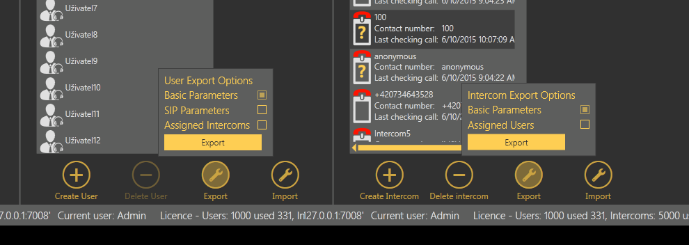 |
Intercom Table Export – Right, User Table Export – Left
Import
The table import function is available in the Intercoms – Users menu. Click Import to open an import window and select a disk location. Select the file to be imported and confirm your selection to import the file and display the lists of imported objects.
Users
The Users menu displays the whole user database defined on the server. The main common part of the menu provides the database searching function: enter the user name (or a sequence of characters) into the search row. The function requires no confirmation and starts searching the database the moment you enter the first character. Add more characters to refine the filter until you find the required user. Click Create user card to add a user to the end of the table. Each user has an icon that identifies its role (function).
| Administrator | Administrator is authorised to make all settings. |
| Superuser | Superuser is only authorised to manage the intercoms and users in its group. |
| Dispatcher | Dispatcher processes the assigned intercom alarm calls via the 2N® Call Center – Communicator application. |
| Technician | Technician is entitled to view the assigned lift settings. |
| User defined | User defined role. |


Click Delete to remove a user. You can use multiselect to delete or select a higher number of users: either hold Ctrl to select the objects or hold Shift to select the first and last objects thus selecting all the objects between them. All the changes made over the selected objects will apply to all of them. Select a user to open an extensive (third) menu level with up to three forms. Let us describe each of the forms.
General
The Users – General menu helps you set personal information on the user: login username and password for the 2N® Lift8 applications.
Note
- Login Name and Password are the only mandatory parameters of this menu. However, you are strongly advised to complete the whole user card correctly!
The other parameters include Firstname and Surname, user function/job Description, Contact number for Technicians or user defined roles without access to the Communicator, Email, Company and Role. New users are created as Dispatchers by default. The following options are available: Administrator, Technician, Dispatcher or User defined role (refer to the Roles and Rights below). Click Save to add the parameters to the database.
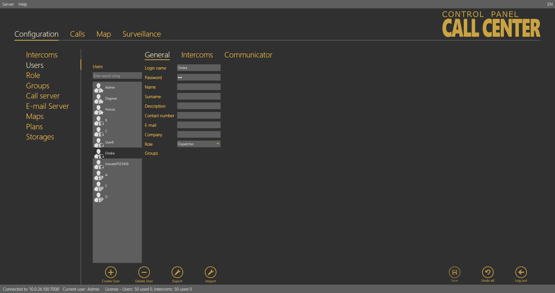 |
Users – General Menu
Intercoms
The Intercoms menu provides a list of intercoms that can be administered and monitored by the user. You can view the checking call results and set some of the intercom parameters depending on your role. Administrator may administer all the system intercoms, users and roles regardless of group assignment. The list of Assigned intercoms displays all the intercoms authorised for the selected user. To add an intercom, select the intercom in the Not assigned intercoms and move it to the Assigned intercoms with the arrow. To delete an intercom, select the intercom in the Assigned intercoms and move it to the Not assigned intercoms with the arrow key. To search an intercom, enter the text or number to be searched into the field above the list and see the filtration result in the associated list immediately. Click Save to save the new settings.
Caution
- Intercoms cannot be moved to/from groups if this would lead to the exceeding of the user license limits.
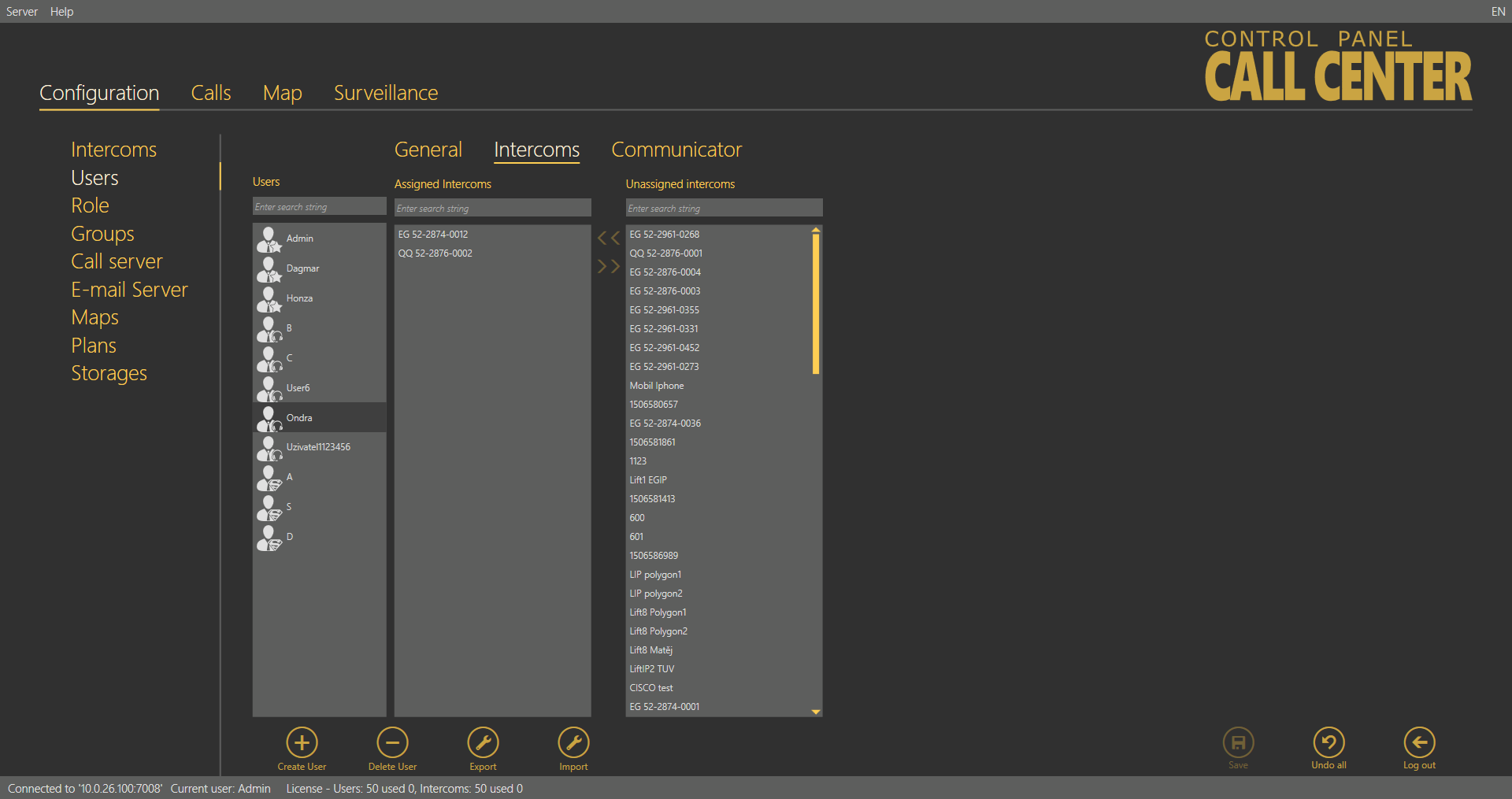 |
Users – Intercoms Menu
Communicator
Every user authorised to use the 2N® Call Center – Communicator must be assigned a SIP line, i.e. an account registered with a SIP provider or the PBX used for login via the 2N® Call Center – Communicator. When you log in to the application, your line will get registered and you can process the calls coming to your line depending on the 2N® Lift8 configuration. An incoming alarm call will probably dial Dispatcher account number. Dispatcher can then contact Technician if necessary. Refer to S.8, 2N® Call Center – Communicator, for details on these functions. Set the following SIP line parameters in the Communicator menu: SIP server and Registrar server, i.e. the server via which the SIP client will register and calls will be made. Enter the IP address/domain of the SIP Proxy server: port 5060 is used by default. If your provider uses a different port, add this port to the Domain parameter behind a colon as shown in the figure below. Set the Domain to differentiate Proxies within a PBX, Username and provide/PBX SIP account Password. Define how often the account shall register with the SIP Proxy in the Registration expires parameter. Find the Local SIP port in the extended Stack settings, which is generated automatically by default but can be changed easily. The Transport SIP parameter defines the protocol type to be used for packet trasnsmission. The transmission uses the UDP.
|
Users – Communicator Menu
Important warning - Upgrade System from ver. 1.5.x to ver. 1.6.x
If you have upgraded an existing database instead of installing a new version, the line settings will not work after upgrade! It is because essential function and configuration changes have been made since the last version and the database could not be transferred completely due to some differences. Thus, modify the configuration as follows to make the system work:
- Keep the Username and Password as they can be transferred correctly.
- Copy the Domain value from version 1.5 into two new parameters: SIP Server and Registrar server.
- Modify the Domain parameter making sure that it does not include a port and includes just the address or domain name.
- Set the Registration expiry and Time limit parameters as necessary.
- Activate the line you have just configured.
- Save the new settings.
After such modification, you will be able to log in via the 2N® Lift8 Communicator and process calls in a standard manner.
Roles
The Roles menu specifies the user login types. The roles define the user rights in the 2N® Lift8 system. Three roles are available by default: Administrator, Technician and Dispatcher. These roles cannot be removed or edited. Click Create role to create a new role and assign access to the functions. See the table below for function details. Click Delete to remove a role. If a role disables a user to view or configure a menu, the menu will not be displayed to the user.
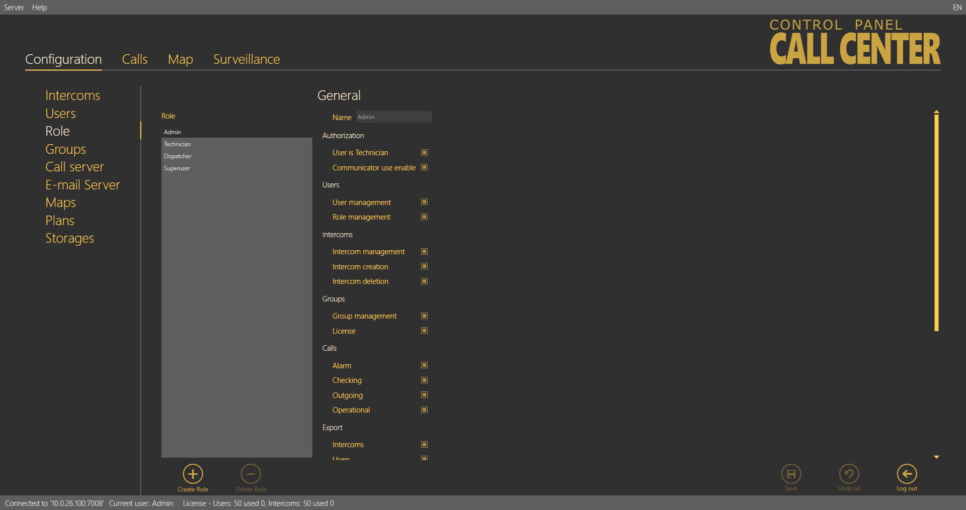 |
Roles Menu
Caution
- If you are editing (updating) rights for an existing role, the user concerned will be logged out when the new parameters have been saved. You will be informed of this by a dialogue window with confirmation.
| Parameter name | Meaning |
|---|---|
| Authorisation | |
| User is Technician | The user is included as Technician in the database and its assignment to the intercom in the 2N® Call Center – Communicator is displayed. |
| Allowed to use Communicator | The user has access to the SIP line settings and may join the 2N® Call Center – Communicator application. |
| Users | |
| User administration | Create, delete and edit all users. |
| Role administration | Create, delete and administer user roles. |
| Intercoms | |
| Intercom administration | Administer intercom databases. |
| Intercom creation | Create a new intercom. |
| Intercom function display | Activate functional/non-functional intercom display. |
| Groups | |
| Group administration | Create, delete and edit user and intercom groups. |
| License | Allow assigning licenses to groups. |
| Calls | |
| Alarm | Display the intercom alarm call database. |
| Check | Display the intercom checking call database. |
| Outgoing | Display the dispatcher outgoing call database. |
| Export | |
| Intercom export | Export the intercom table. |
| User export | Export the user table. |
| Call export | Export the call table. |
| Import | |
| Intercom import | Import the intercom table. |
| User import | Import the user table. |
| Surveillance | |
| Global map | Display the Surveillance menu. |
| Others | |
| Call Server | Make Call Server settings accessible to the user. |
| Plans | Make plan list and settings accessible to the user. |
| Storages | Make server storage creation accessible to the user. |
| Email server | Make Email server settings and management accessible to the user. |
Groups
The Groups menu helps you define intercom groups for easier configuration of multiple objects and separation of lift administering firms. The first option helps you configure all intercoms assigned to one group (in one building, e.g.) at one time. The other option helps you manage multiple companies on one server as separate groups. Administrator assigns intercoms and users to each group to be administered by the appropriate group Superusers.
Tip
- You can combine the two options to a certain extent. However, remember that the main structure users cannot see the group users and that there are some security risks due to extended user rights.
- If you define groups with own Administrator - Superuser rights, we recommend that the Administrators - Superusers themselves configure the users to be administered to eliminate potential problems in the future.
Intercoms and users can only be added to a group by Administrator or Superuser. Now let us describe what you can configure in the Groups menu. There is a list of all objects called Intercom groups to the left. To find a group, enter the user name (or a sequence of characters) into the search row. The function requires no confirmation and starts searching the database the moment you enter the first character. Add more characters to refine the filter until you find the required group. Click Create group to create a new group and add it to the end of the list. Click Delete to remove a selected group. Click Save to confirm the settings.
 |
Groups Menu – General
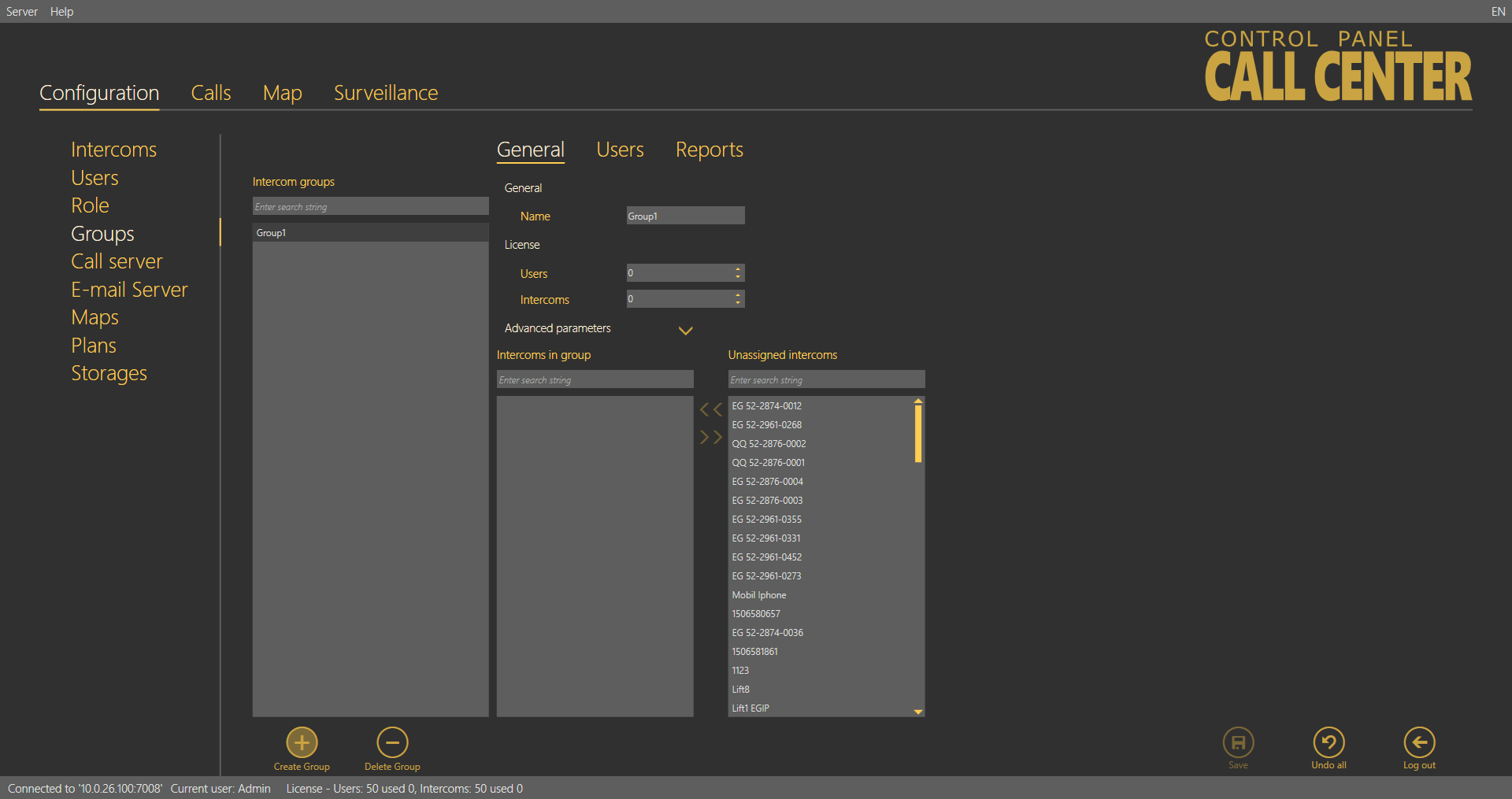
General – Administrator
Rename a group in the Name parameter in the Groups – General menu. Specify the maximum count of licensed objects (intercoms and users) in the Licence parameter to be assigned to a group. Administrator finds the current use of licensed objects in the application status row. The other users cannot view this setting. Furthermore, you can assign intercoms to a group. You can see a list of all created intercoms not assigned to the currently displayed group to the right and a list of all intercoms assigned to the group to the left. You can use the searching function like in the group list. Select an intercom and click the appropriate arrow to move the intercom to/from a group. You can use multiselect for selection. Furthermore, the menu provides an extended setting, which helps you assign all the parameters at once to the given intercom group. Define the Type of device: 2N® LiftNet, 2N® SingleTalk, 2N® Lift8 or Unknown; refer to the Intercom Creation subsection above for details. Plan is the next parameter: enter the Address of the building where the intercom group is installed and intercom positions on the plan. This information will then be displayed on the map for Technicians or Dispatchers to repair the device or navigate the rescue team respectively. The Checking call period defines the timeout for the intercom to check-call the 2N® Call Center – Server. The intercom can call the 2N® Call Center – Server any time within this timeout, but having exceeded this value, it will be marked as defective. The non-functional status will be removed when another checking / alarm call arrives in the server from this intercom. The default value of this parameter is 72 hours. The Alarm call response specifies the type of alarm call processing: Normal call, CPC Antenna, CPC KONE and P100. Similarly, the Checking call response specifies the type of checking call processing: Reject, Accept and send 5, Confirm with 1 a 5, CPC Antenna, CPC KONE and P100. Click Set intercoms to confirm the settings and execute changes in all the intercoms assigned to the selected group.
Caution
- If DB_COMMUNICATOR is set in the Checking / Operational call response intercom menu, every missed call is marked with a red phone symbol and a missed call message is displayed in the Calls / Alarm menu.
If the call is received by a third party, a green phone and a call receiving message are displayed in the Calls / Alarm menu.
If DB_COMMUNICATOR is selected, no checking calls are received via the intercom and no information is displayed in the Calls / Checking folder. - The same feature as in the DB_COMMUNICATOR parameter is implemented for the last intercom list line. This means no checking and operational calls are received and all calls to the line are in a mode identical with DB_COMMUNICATOR.
Tip
- Administrator is the only user authorised to set the licence parameters!
- Advanced settings are not required. You can configure all or no parameters at your discretion.
- The advanced parameter list is empty by default. If a parameter is identically set for all the intercoms, the parameter value will be displayed. If not, the field will remain empty.
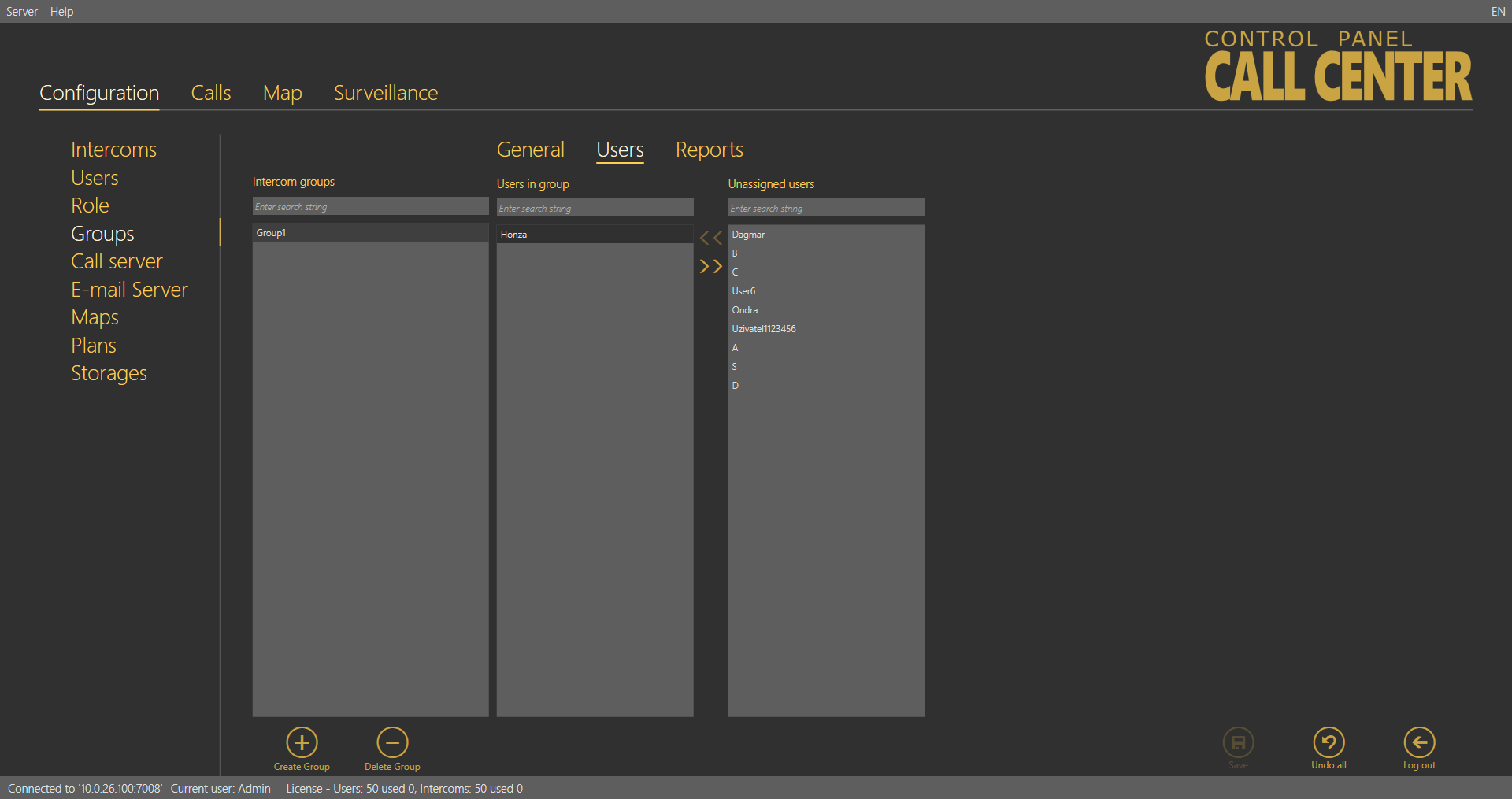
Users – Administrator
The Users menu provides a list of users that are authorised to administer and monitor the intercoms in a group. Administrator may administer all the system intercoms, users and roles regardless of group assignment. All the users authorised for the selected group are displayed in the list of Assigned users and next to the intercoms. To add a user, select the user in the Not assigned users and move it to the Assigned users with the arrow. To delete a user, select the user in the Assigned users and move it to the Not assigned users with the arrow key. To search a user, enter the string to be searched into the field above the list and see the filtration result in the associated list immediately. Click Save to save the new settings.
 |
Groups – Users Menu
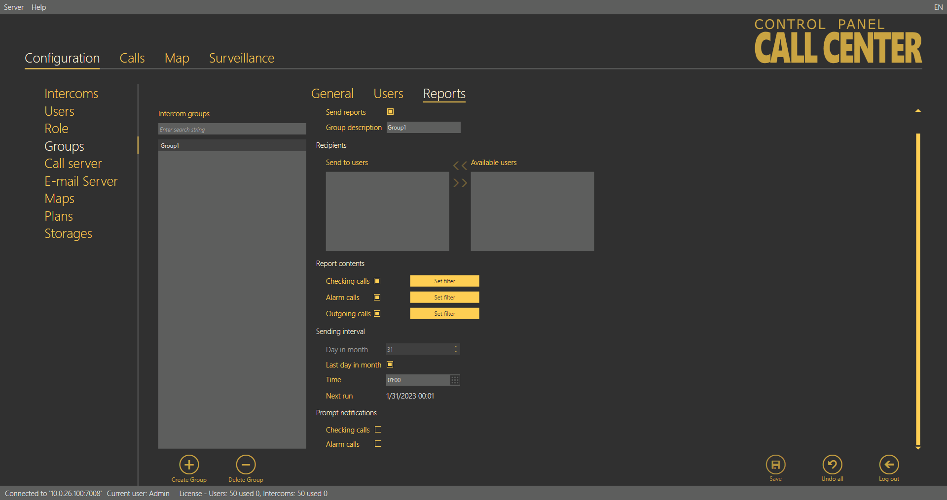
Reports – Administrator
The menu enables report sending. Selected users can send messages above the framework of general statistics sent by the Email server. The reports always refer to the group to which they are assigned and are only sent to the recipients included in the list. Make sure that a correct email is defined for every user on the list in the Users - Basic menu to allow for proper report sending.
 |
Groups - Reports Menu
Let us describe the menu controls now. Select Send reports in the Report activation section to enable report sending for the given group. Make sure that the outgoing server is configured in the Email server menu to make the function work properly. Otherwise, the reports will be set but not sent automatically. When reporting is enabled, the appropriate settings will be activated. Select a recipient from the list of Available users in the Recipients section and use the arrow to move it to the Send to users list. Remove the user analogously. The Available users only display the users that are assigned to the given group and whose email addresses are completed. Specify the reports to be sent in the Reports content section using the checkbox. Define the content of the email to be sent in the Email server – Report settings menu. Define the Sending interval for the reports: Next run will generate the time of your next report sending. Enable prompt notifications using the last checkbox to send information on a new situation immediately.
Superuser
Superuser is a system user that is assigned some Administrator rights. Superuser is assigned to a group, obeys the group setting rules and applies its rights only within the group assigned to it, thus substituting the Administrator function for the given group. Superuser is not allowed to create or delete a group, but may rename a group and add users and intercoms. Superuser never gets an intercom to a higher level without group assignment. This may be done by Administrator only. Moreover, Superuser is not allowed to set licences, but may monitor licences and ask Administrator for increasing licensed objects if necessary. Superuser can also add and edit plans in the group(s) assigned to it by Administrator.
Caution
- Remember that Superuser assigned to no group has similar rights as Administrator in the whole database upon login. Therefore, be very careful while assigning groups to avoid security risk or data loss.
Tip
- Adding a user or an intercom, Superuser is always asked about its group assignment. If Superuser is assigned to one group, the new object will be added to this group automatically. If Superuser is assigned more groups than one, a list of assigned groups will be displayed. Superuser sets the object name and selects a group for the object.
- Group users may only view the objects (users, intercoms, plans) as specified by their rights.
- Superuser cannot view the Local plans added by Admin. It can only view the plans assigned to its group added either by Superuser or any other user in the given group. Superuser cannot set and/or change any plan that is not assigned to the group. If, however, Administrator adds a plan, any user can display the plan in the intercom menu.
Call Server
The Call server helps you configure the SIP lines for the CU checking calls. Configure up to 8 independent telephone lines. The first line is also intended for active checking calls and can be configured via extended settings. Enter the SIP line parameters correctly for a successful SIP Proxy server registration. Make sure that the lines and servers are configured correctly to make the Call server work properly. If you use VoIP, obtain the SIP line settings from your VoIP provider. If you have a SIP Proxy server of your own, contact your network administrator for correct settings.
Caution
- Set the SIP lines in the 2N® Call Center – Server! Use the settings of the PC on which the server is installed instead of your PC settings. Your PC settings will be applied only if the server runs locally.
The List of available lines displays all of the 8 lines to be configured. Each line includes identification and state parameters: Domain specifies the domain with which the line is registered, Active shows whether the line is currently on/off and Active calls counts the current calls via the line. If Active calls is zero, there is no active incoming/outgoing call on the line. The Active checking call function is enabled for the first line.
 |
Call Server Menu
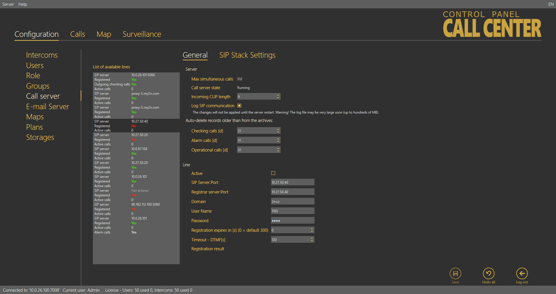
General
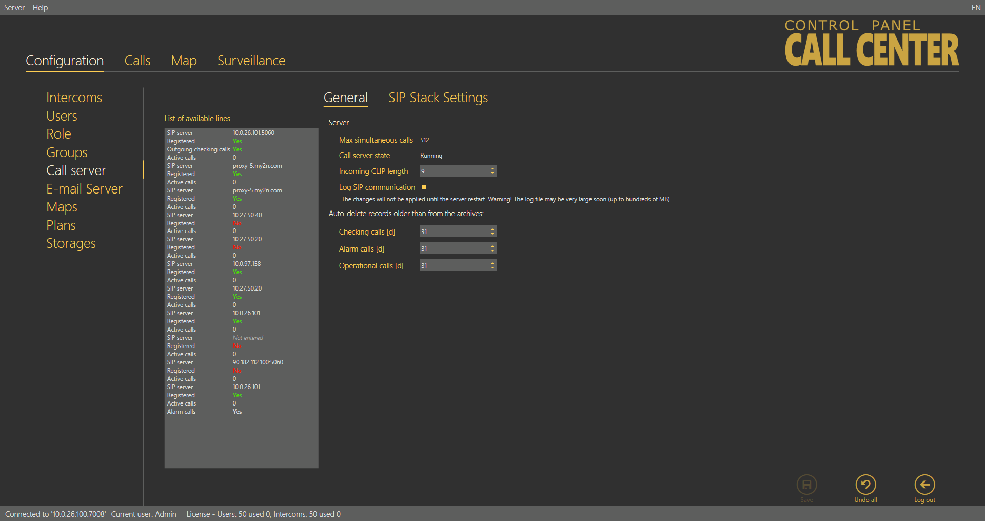
The General menu consists of two parts: Server for all the lines and Line. Server provides the current SIP server state information:
Maximum simultaneous calls – displays the maximum count of checking calls to be processed by the server at the same time. If more calls than as defined in the parameter arrives in the server at one moment, all the excess calls will be rejected.
Call server state – signals the current state of the server: Starting, Running, Waiting for reconfiguration and Error.
Caution
- If in a state other than Running, the Call Server rejects all calls coming to it, i.e. does not receive or process any checking calls.
The Incoming clip length – compare and assign contacts to matching phone numbers. This avoids contact duplicity in the case, e.g., that a contact is stored once as a 6-digit number without a code and once as a 9-digit number including the +420 code. The function evaluates the match from the end starting with the last contact digit and proceeding to the first. The count of digits to be match can be set. If no match is found, a new intercom is created.
Log SIP communication – select this parameter to activate Trace to trace all SIP server communication. Once enabled, the parameter creates a pjsip.log file in the log directory for the logs captured.
Caution
- Caution! Do not keep SIP communication logging enabled for too long to avoid extreme log file sizes (up to hundreds of MB) due to high frequency of incoming calls. Use this function for error diagnostics only.
Auto-Delete of Records from Archive Older Than
These two parameters monitor the age of the checking and alarm call database records and delete the oldest ones to avoid an extreme growth of the database and rapid slowdown of the application and server operation. Set the parameters in days. The parameters work as follows.
An incoming check/alarm call is added to the primary call database, where the last three calls from each intercom are always stored. When another (fourth) call comes in, the oldest call will be moved automatically to the secondary call database for a user-defined period of time. When the user-defined interval elapses, the call will be deleted from the secondary database and stored nowhere on the server. This happens when the intercom works normally, the above-mentioned call is followed by another checking call and the old record need not be stored any longer. If, however, no more calls come from the intercom, the last call will not be deleted, but stored as evidence of the last checking call attempt. In practice, the database always stores three calls at least from each intercom phone number if accomplished. If the intercom never called more than once, there will be just one call in the database.
Tip
- Click Load calls from archive in the Calls menu to load the secondary call database.
Warning
- If you set the parameters to the minimum value (3 days), all calls will be deleted irretrievably after being moved to the secondary database.
Line
Complete the line parameters, select Active and save the new settings to activate a new SIP line. This activates the Registration result and sends the registration packet. The registration result is then displayed and the identification in the list changes from No to Yes. See below for details.
Note
- Enter SIP Server, Registrar server and Username at least to configure a valid SIP line.
Select/unselect Active to activate/deactivate the selected line. Enter the SIP Proxy address into the SIP Server:Port field. The port is optional. If you set just the Proxy address, the default port 5060 is used. If you choose another port, add this port behind a colon. Enter the SIP Proxy address for login into the Registrar server parameter. The port is optional. If you set just the Proxy address, the default port 5060 is used. If you choose another port, add this port behind a colon. Domain specifies Proxies within one SIP server. Unless specified otherwise by your provider, the domain will be SIP or Registrar server, yet without a port. See the figure above. Complete the Username for your SIP Proxy server authentication and Password if the Proxy requires so. Registration expires after is an optional parameter. The default value is 300 s, but some servers may require a different value, which will not be changed. Set the Timeout – DTMF in seconds: 120 s is the default value. If no DTMF arrives within this timeout after answer, the call will be terminated. Registration result displays the SIP Proxy registration result. If unsuccessful. the registration packet will be resent. This parameter is updated automatically. When you click Save for confirmation, the registration packet will be sent to the server immediately. If everything is OK, the following message header will be displayed in the Registration result: "Registered, Code: 200, OK". To deactivate an active line, select the line and unselect the Active checkbox. Click Save to confirm the setting.
Tip
- Contact your network administrator or VoIP provider for correct SIP line settings.
- If registration fails, you will find the error code (SIP error message) in the Registration result. If your registration data are correct, contact your network administrator.
Important warning - Upgrade System from ver. 1.5.x to ver. 1.6.x
- Keep the Username and Password as they can be transferred correctly.
- Copy the Domain value from version 1.5 into two new parameters: SIP Server and Registrar server.
- Modify the Domain parameter making sure that it does not include a port and includes just the address or domain name.
- Set the Registration expiry and Time limit parameters as necessary.
- Activate the line you have just configured.
- Save the new settings.
Go on like this with all the other lines. After such modification, the call server will start processing calls in a standard manner.
SIP Stack Settings
Caution
- The SIP stack settings are common for all the server lines and all the 2N® Call Center – Communicator users.
Set the Local SIP port, which is generated automatically by default but can be changed easily. The Transport SIP parameter defines the protocol type to be used for packet trasnsmission. The transmission uses the UDP.
 |
Call Server / SIP Stack Settings Menu
Warning
- All changes made in this menu will not be applied until the server is restarted manually! It is necessary to read the SSL libraries, which are not needed in common operations.
- Restart the server in the Services system menu or via the 2N® Call Center l8-config.exe application. Refer to Subs. 6.2. for function details.
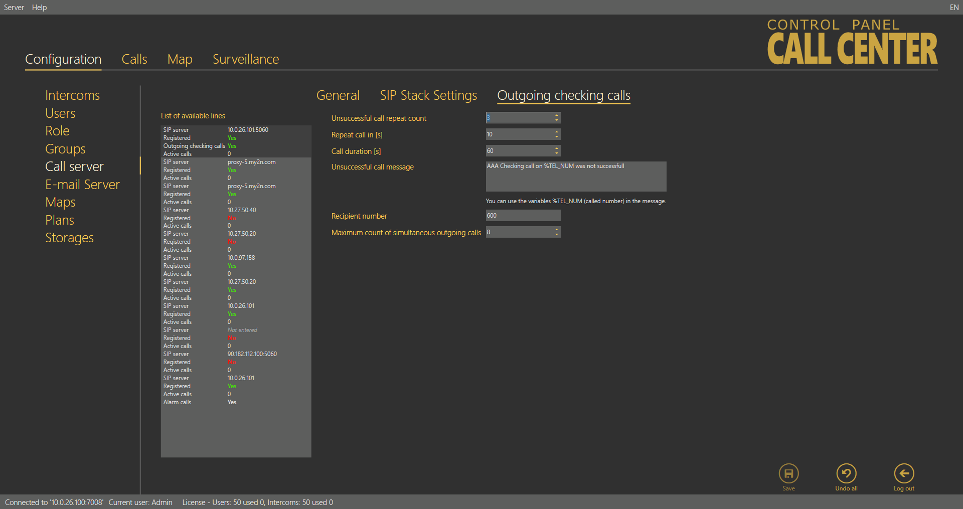
Outgoing Checking Calls
This menu is devoted to outgoing checking calls and their settings. The following parameters are defined here: Unsuccessful call repeat count defines the count of calls to the intercom before an error is detected. Repeat call defines the interval between the attempts. Call duration sets the maximum call timeout after which the Call server hangs up automatically. You can define an Unsuccessful call message to be sent in case the intercom is inaccessible and marked as defective. You can insert the string %TEL_NUM in the message to provide the inaccessible intercom contact number. Complete the Message recipient number including the correct dial-in if necessary. Maximum count of simultaneous outgoing calls specifies the count of calls to be processed by the server at the same time. Respect the capacity of your outgoing gateway while completing this parameter.
 |
Outgoing Checking Calls Menu
Tip
- If your outgoing gateway has 4 channels, make sure that the Maximum amount of simultaneous outgoing calls does not exceed 4. Otherwise, the server would try to make more calls than the gateway is able to process and the excess calls would be rejected. The server would thus be marked as non-functional after several rejections.
Email Server
2N® Call Center – Server is equipped with an email client that provides connection to the SMTP server and helps send reports on intercom states. The menu has two parts: SMTP Server Settings, which helps you set the report sending account, and Report Settings for detailed report settings.
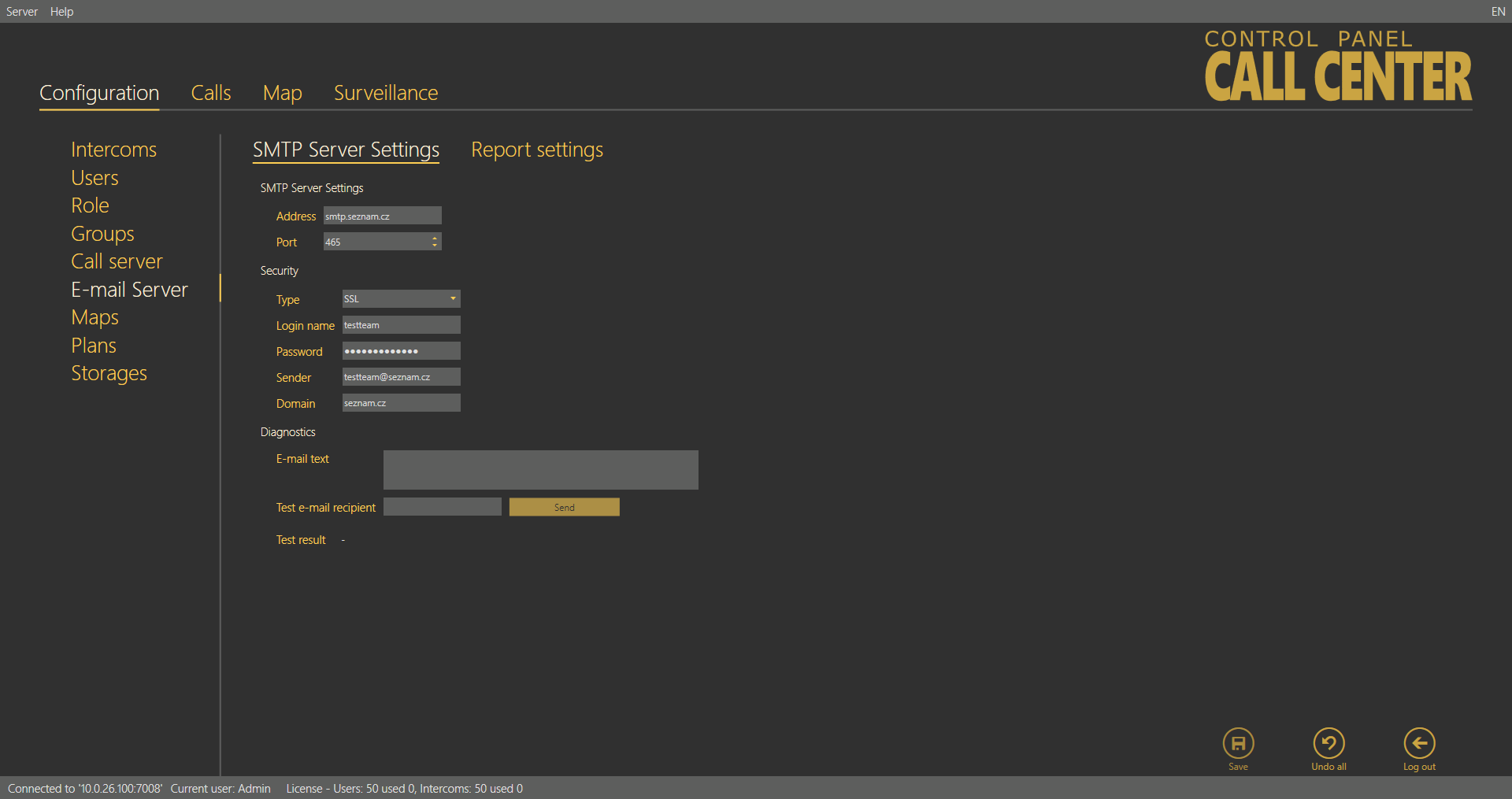
SMTP Server Settings
Address and Port are the first parameters of the menu. Set any SMTP server that supports insecure connection on port 25 as the Email server is not intended for encrypted SSL communication. Then complete the Security items – User name and Password for authentication – as communicated to you by your network administrator. Select the required functions in the Report activation section. Enable periodic reports to make the server generate and send a report automatically at a defined time on a selected day. Enable sending of prompt notifications to watch all the intercoms and send error state information immediately regardless of the periodic report interval. Email sending diagnostics helps you define a text and test email recipient of your own to test the correct client setting for SMTP email sending.
 |
Email Server – SMTP Server Settings Menu
Note
This function does not work if a two-factor authenticated e-mail account is used.
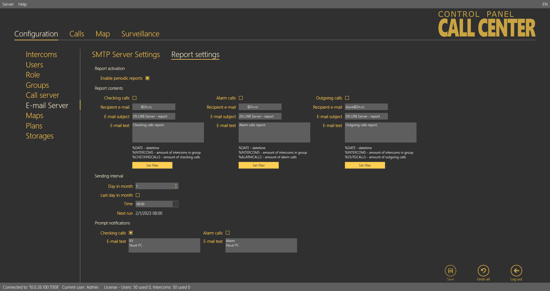
Report Settings
Define the content of the email reports to be sent. Four types of notifications are pre-defined here: checking, alarm and outgoing calls and prompt notifications. Set the contents of the three report types as follows: Select the report recipient email address or set groups on the provider's SMTP server for group/bulk sending. Then define the email subject and text (body). You can use a string to be replaced with the current intercom count or date. Refer to the list of supported strings below the report body. At present, the following strings are supported:
| %DATE | Date and time |
| %INTERCOMS | Intercom count |
| %CHECKINGCALLS | Checking call count |
| %ALARMCALLS | Alarm call count |
| %OUTGCALLS | Outgoing call count |
Set a filter for each report type: select the calls you are interested in (error or missed calls, for example). The filters are the same as in the Calls menu. If no filter is set, all calls are displayed. Enable prompt notifications and set the text of the report to be sent to distinguish prompt notifications from periodic reports. Prompt notifications are automatically sent to the email address completed for the given situation whenever a change occurs.
Caution
- An instantaneous notification of the checking call is sent the moment the set checking call timeout expires. An instantaneous notification of the alarm call is sent the moment the alarm call to the communicator is ended.
- The sending time limit for the instantaneous alarm/checking call notification is 5 minutes.
|
Email Server – Report Settings Menu
Note
- Select Enable periodic reports and Send prompt notifications in the SMTP Server settings to enable sending of periodic reports and prompt notifications.
Define the Sending interval for periodic reports. Set a day in the month and time for the report to be generated and sent. Select the Last day in month to generate a report on the last day of the month regardless of the count of month days and define the hour.
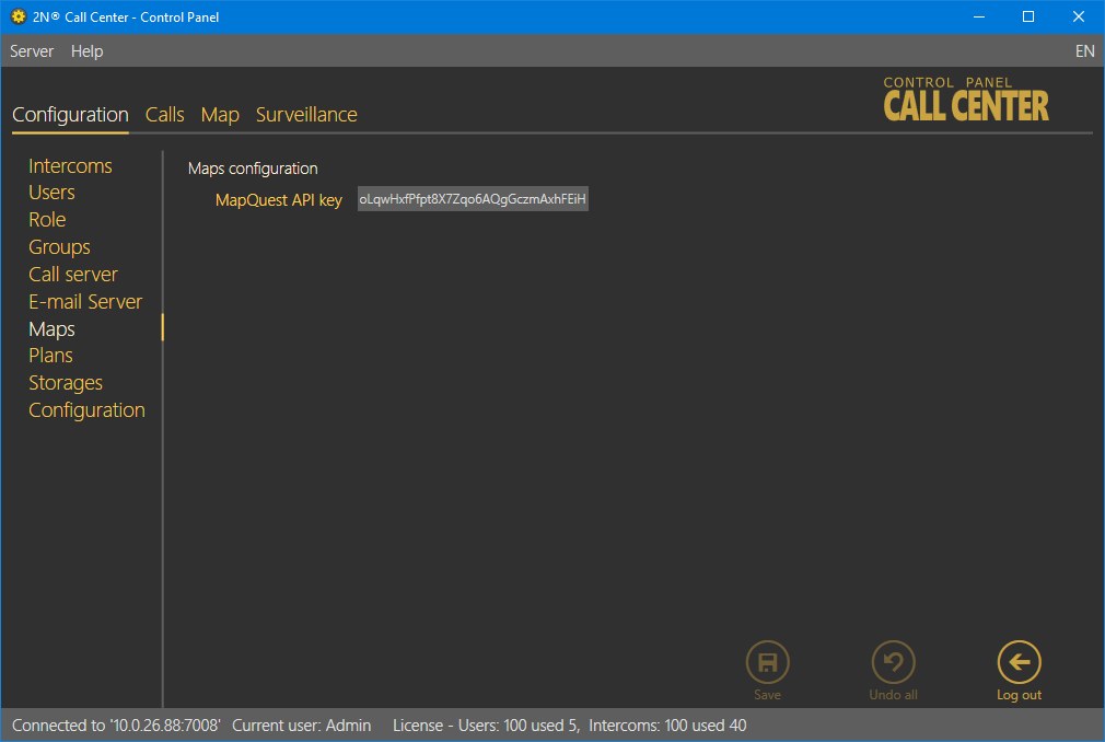
Maps
This menu provides interconnection with the developer.mapquest.com account when the appropriate MapQuest API key is entered. The interconnection with a dedicated account is essential for a proper function of the program, avoiding map loading failures.
 |
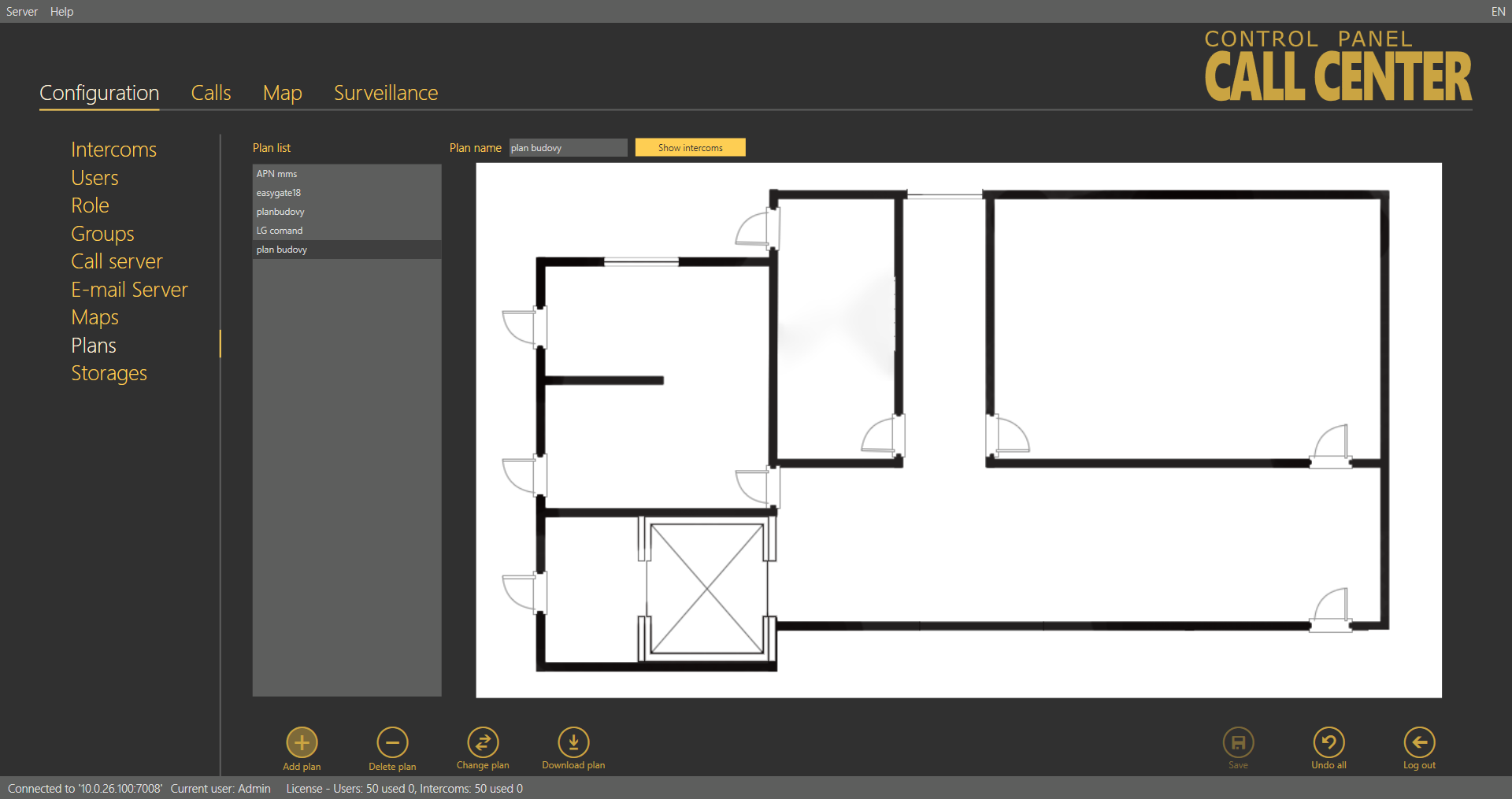
Plans
The Plans menu helps you manage plans of the buildings in which the intercoms are installed. Assign the plans to the selected intercom and mark the intercom position in the Intercoms menu. This information will then be displayed to the 2N® Lift8 Communicator operators.
 |
Plans Menu
Click Add plan to open a file browser and select the file to be added. Refer to the right part of the screen for the figure to be imported. Click Save to confirm the new plan.
Tip
- All the saved plans are stored in the 2N® Call Center – Server and accessible to all the logged-in users.
Caution
- If, contrary to the figure, information is displayed instead of the plan list, check the plan storage on the server. If the storage is not configured, set its parameters in the Storage menu.
- If the Storage menu is unavailable, enhance the user rights.
Note
- Insert figures in the PNG, JPG or BMP format.
- The file browser is configured for PNG by default. If you cannot see the figures in the folder, change the file format (typically, in the right-hand upper corner next to the file name).
Click on the plan to display the preview. Click Show intercoms next to the Plan name to view all the configured intercoms as an intercom symbol plus the phone number; see the figure above. Click Remove plan to delete a plan. Click Change plan to update a plan while keeping the plan name and the current intercom structure. Select Download plan to save the plan without the intercom positions onto a local disk.
Tip
- Plan changing is useful when you need to update a plan after reconstruction and interior changes while keeping the existing intercom structure in the building.
Caution – exceeded maximum storage size
- Plans are saved sequentially. The error displayed always relates to the currently saved error-state plan. The other plans are queued for saving.
- When the error is solved (by deleting of the 'defective' plan, e.g.), saving can go on as the Save button keeps active.
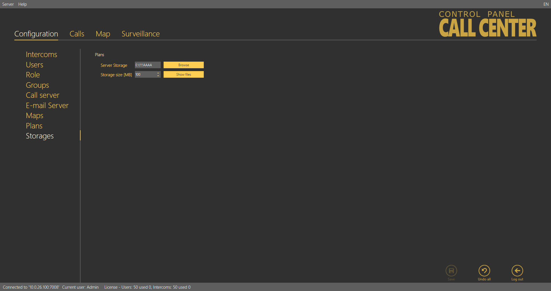
Storage
The Storage menu helps you configure all the storages necessary for the operation of the 2N® Lift8 system services. You can map the storage folders on a local disc, network discs and such additional memories as USB discs and memory cards.
 |
Storage Menu
You can map the path for plans: click Browse at the given storage to select the path to the folder to be used for storage. You can also create a new folder in the path selecting window. Now set the maximum Storage size (data space) within the whole logic storage (disc C, e.g.). Click Save for confirmation. From now on the storage will be active and used for data storing. Click Show files to view the files and plans stored on the disc. Their names correspond with the server database key. You can also see the file size and delete any file in this window.
Tip
- The file name is encoded to eliminate building identification for security reasons.
- Press F2 to rename a new folder.
Caution
- When the storage is full, no new plans can be added. Delete the old plans or set a higher storage capacity.
Calls
Calls is the other part of the main menu. This menu contains tables with checking and alarm calls of all the intercoms and dispatcher and technician outgoing calls. The call history starts with the first server installation and the whole call database is always read, which facilitates call search. You can also use filtration to find the required call. Set a filter for each column and combine the filters to find the required data as soon as possible. Click the funnel symbol in the selected column to activate the filter. Activation is indicated by a colour change of the funnel symbol; see the figure below.
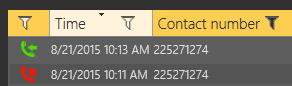 |
Left – Inactive Filter, Right – Active Filter
Each column with the funnel symbol includes specific filter settings; see the figure below. The Contains function finds the searched string in all the column items and returns all the occurrences. Enter a text into the string field and click Filter to activate the filter and find all the searched items in the column. Use another filter to make your search more precise and efficient. Having completed filtering, click Delete filter in the used columns to delete all the active filters.
Tip
- You can also delete the filters via the contact menu displayed by clicking the right mouse button anywhere in the table or using Alt + r.
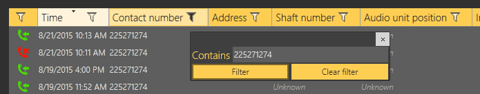 |
Filtration Setting Result
The first column of icons defines the call states. Column filtration can be used for explanation: choose which call state to filter. This information is available in all the three menus yet with different, specific meanings.
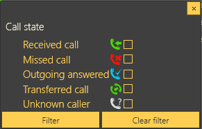 |
Alarm Call States
The states are described successively. Received call is the first state, which indicates a correctly processed incoming alarm call. The second icon, Missed call, means that the dispatcher failed to answer the call in time for any reason and ringing has been terminated. The Outgoing answered icon means that the dispatcher failed to answer the call in time for any reason and ringing has been terminated. The dispatcher is notified of this fact, calls the lift and gets connected to the alarm-initiating audio unit. This call is then evaluated as a correctly processed alarm call. Transferred call means that the dispatcher transfers a confirmed alarm call to another dispatcher or technician. The last state, Unknown caller, gets displayed whenever a completely unknown number is calling the server, i.e. the number is not included in the server configuration or is CLIR.
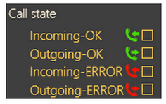 |
Checking Call States
The first state (top icon) is Incoming – OK, which signals a correctly processed incoming checking call and typically appears for rejected checking calls and checking calls with confirmation or via CPC and P100 whenever the communication is OK and the call is terminated correctly. Outgoing – OK appears for correctly made outgoing checking calls to the intercoms configured. Incoming – ERROR and Outgoing – ERROR mean that an error occurred during the call course and evaluation (CPC/P100 failure, e.g.).
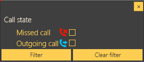 |
Outgoing Call States
The states are described successively. Missed call means that the dispatcher failed to answer the call in time for any reason and ringing has been terminated. The Outgoing answered icon means that the called person failed to answer the call in time for any reason and ringing has been terminated. The called party then calls the dispatcher itself and the call is evaluated as correctly processed.
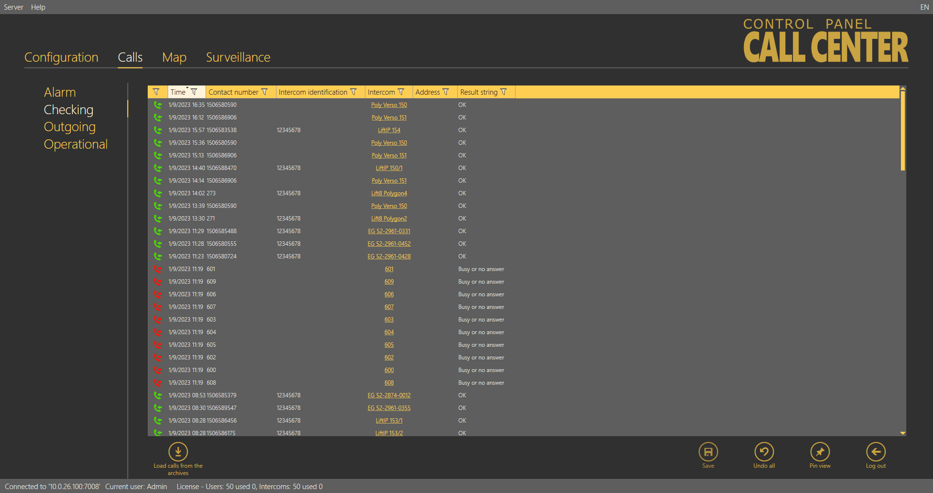
 |
Operational Call States
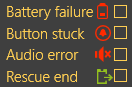
The states are described successively. The first icon indicates a battery failure and is sent whenever the battery capacity is too low or the batteries are older than 2 years and need periodic replacement. Button stuck means that the Alarm button is jammed due to a mechanical defect or sabotage. Audio error means that the automatic audio unit audio test has failed due to a technical defect or sabotage (vandal damage to the microphone or speaker, e.g.), which disables proper communication with the control room. Rescue end signals that the cause of alarm has been repaired on site and the lift is fully functional again. In that case, the CU ends the rescue mode and calls the server to end the rescue mode too automatically.
The Calls menu is the only menu to include the Pin view button. Push the button to open the call history table in a new window. This allows you to view the call list on one monitor and configure other intercom and user parameters on the other; see the figure below.
 |
Pin View
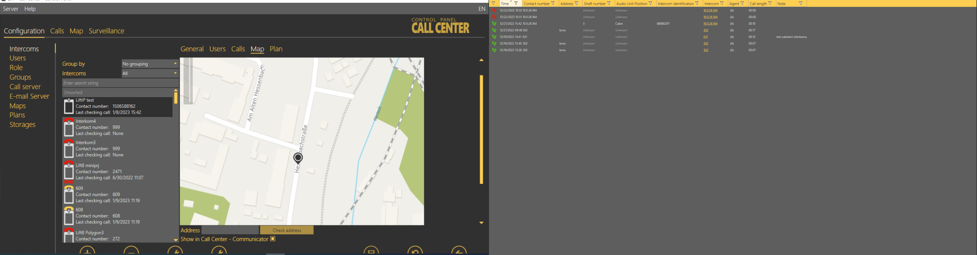
Alarm Calls
The Alarm calls menu provides a table of all the alarm calls from all configured intercoms received by the 2N® Call Center –Server from intercom addition until now. Click the filter button at each column to use filtration for call history search. See above for details. The table provides the following information: call state, Timestamp, Contact number, Address, Shaft number, Audio unit position, Intercom identification if CPC/P100 was successfully used, Opponent name and call-processing Agent/Dispatcher name. The last table column Note shows the note entered by the dispatcher during the alarm call. Click Load calls from archive to load the secondary call database as described in the Calls Server subsection above.
 |
Calls – Alarm Menu
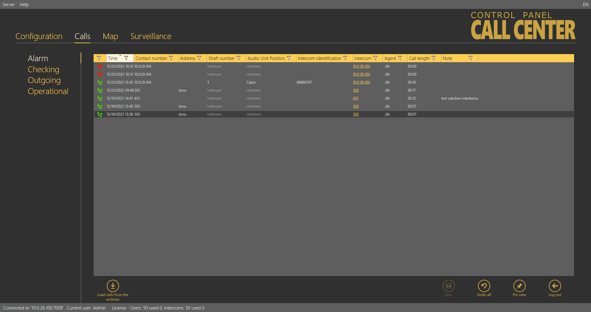
Checking Calls
The Checking calls menu provides a table of all the checking calls from all configured intercoms received by the 2N® Call Center – Server from intercom addition until now. Click the filter button at each column to use filtration for call history search. See above for details. The table provides the following information: call state, Timestamp, Contact number of the calling CU, Intercom identification if CPC/P100 was successfully used, Intercom name, Address and Result string. See the figure below. Click Load calls from archive to load the secondary call database as described in the Calls Server subsection above.
 |
Calls – Checking Menu
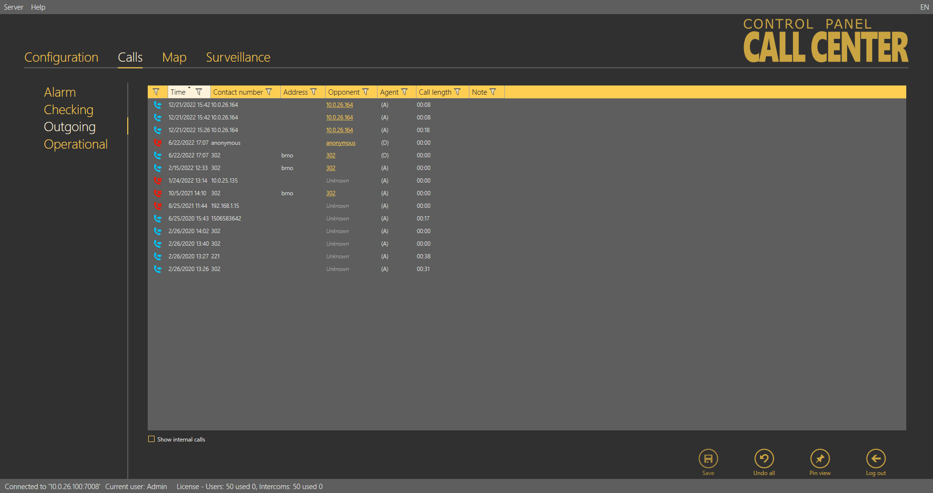
Outgoing Calls
The Outgoing calls menu provides a table of all the outgoing calls from all users (Technicians and Dispatchers) received by the 2N® Call Center – Server if made via the 2N® Call Center – Communicator. Click the filter button at each column to use filtration for call history search. See above for details. The table provides the following information: call state, Timestamp, Contact number, intercom Address, Opponent number and call-processing Agent name. The last table column Note shows the note entered by Agent during the alarm call. Click Load calls from archive to load the secondary call database as described in the Calls Server subsection above.
 |
Calls – Outgoing Menu
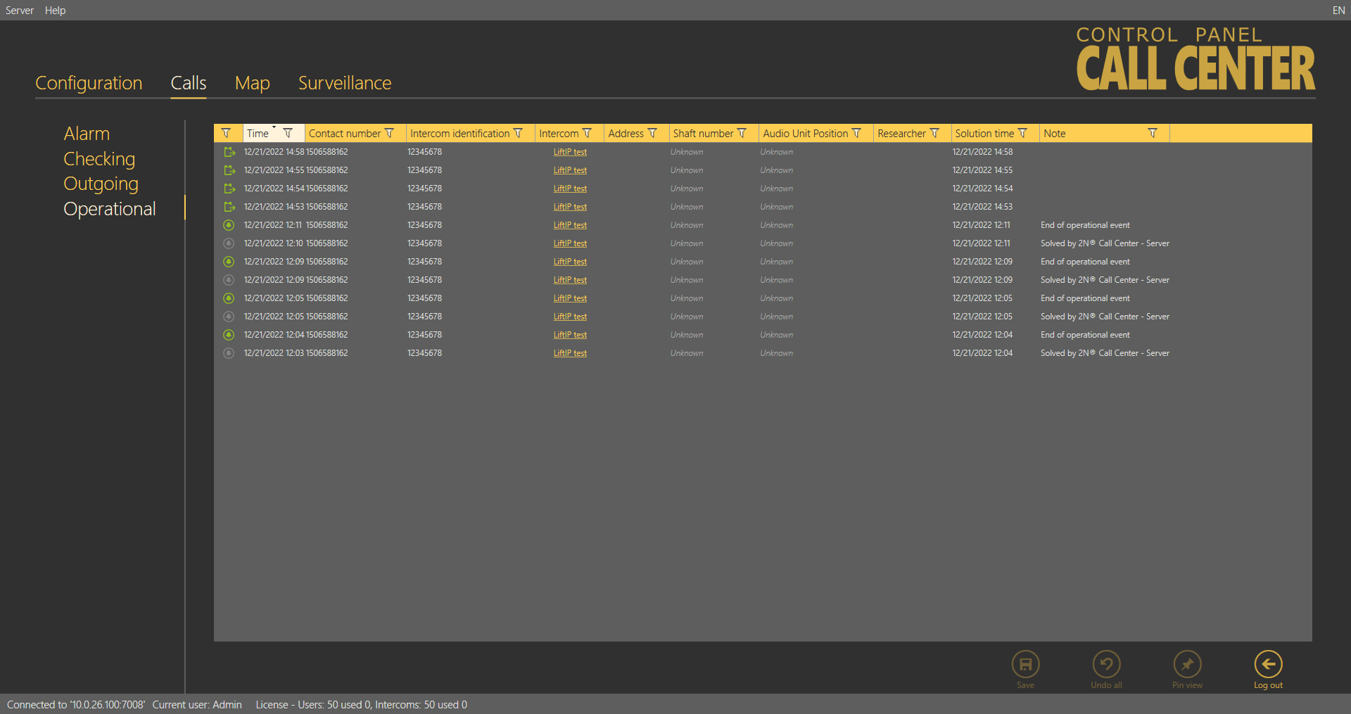
Operational Calls
The Operational Calls table includes all operational calls from all the intercoms recorded by the 2N® Call Center – Server. The condition is that the calls are made via a 2N® Lift device that supports this type of calls. Press the filter in the respective column to search the call history. See above for details. The table provides the following information: call state, call date and time, called number, intercom address and Id, intercom contact number and, if necessary, a note specifying the operational event ending type (automatically, by server). Thus, press the button to solve the error event in the Intercoms - General menu. Press Load calls from archive to load calls from the secondary database described in the Call Server subsection.
 |
Calls – Operational Menu
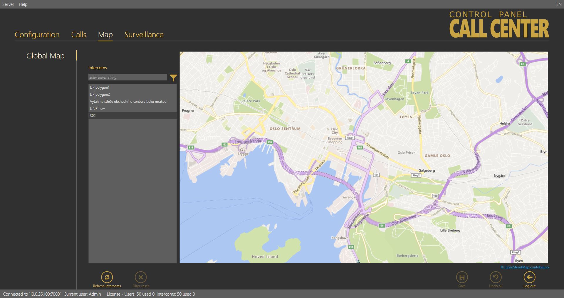
Map
The Map menu helps you monitor the states of all intercoms configured in the system. It displays a list of all the intercoms that are assigned address, which is important for the world map location. A live map with groups of intercoms is displayed next to the list. Colours indicate the intercom state: green means that the intercom is functional, red signals a defective intercom due to a checking call error, orange indicates that an intercom is OK now as the last checking call was correct but the last but one checking call was wrong and green reappears when a non-functional intercom makes a correct checking call.
 |
Map – Global Map Menu
Click on an intercom to focus on the currently selected intercom. Click on another intercom to centre this object. You can move and zoom in/out the map arbitrarily. You can use the search function to find the required intercom: enter the intercom name (or a sequence of characters) into the search row. The database search starts the moment you enter the first character. Add more characters to refine the filter until you find the required intercom. Click the Refresh intercoms button in the left-hand bottom corner to refresh all the intercoms on the map.
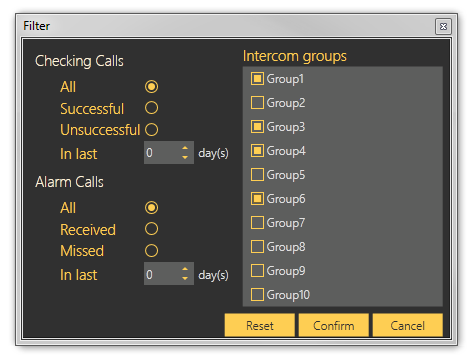 |
Map – Filtration Menu
Click the funnel symbol to display the intercom filtration window. Select a group of intercoms and click Confirm to display the intercom group to be searched. Use more filtering criteria to optimise your search: successful checking or alarm calls or error checking calls in the last x days (see above). All calls are displayed by default. The search result is shown in the Map menu – Global Map figure above.
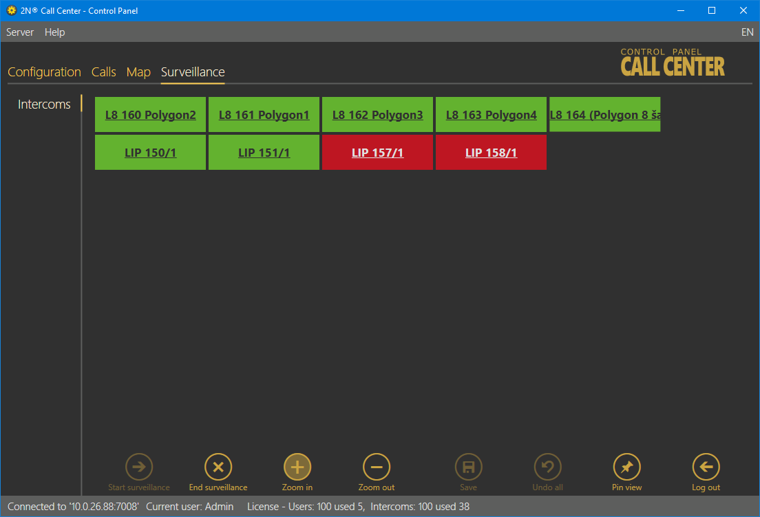
Surveillance
The Surveillance menu displays and helps you monitor all of the configured 2N® Lift8 or 2N® LiftIP intercoms providing data tunnel communication. There are three possible intercom states: red indicates that the intercom is not connected to the Server or shows a problem, which is described in the hint under the cursor, blue means that the unit is server connection ready and green signals OK. Click the intercom field to move to the Basic/Intercom detail tab in the Intercoms menu.
 |
Surveillance Menu
Enter the menu to start watching the available intercoms. Click the Start / End watching buttons in the left bottom corner of the screen to connect new intercoms or quit surveillance.
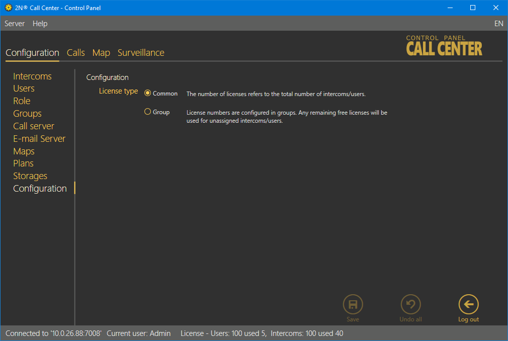
Configuration
If Common is selected, the license is valid for every user and every intercom independently of their asignments to groups.
If Group is selected, the total intercom count corresponds to the sum of allowed intercoms in groups and intercoms outside groups. The total count of intercoms in groups includes all places in groups independently of whether they are currently occupied by active intercoms. Example: Suppose 3 groups are set. Up to 10 intercoms can be added to each of them. 5 intercoms are placed outside the groups. The function needs a license allowing at least (3 × 10 + 5 =) 35 intercoms.
 |