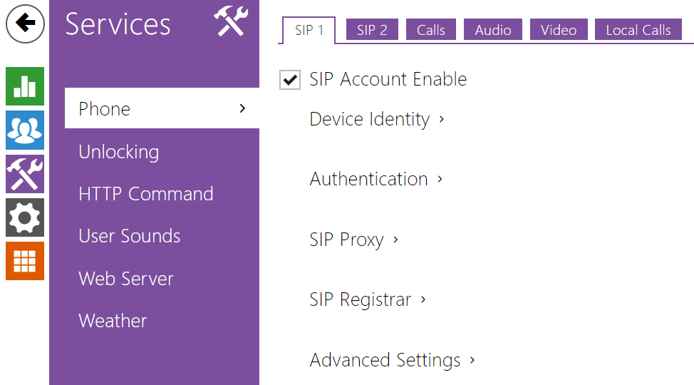
3.2.3.1 Phone
 |
Phone is the essential function of 2N® Indoor View allowing you to establish connections to other IP network terminals. 2N® Indoor View supports the extended SIP.
List of Parameters
2N® Indoor View Phone includes the following four tabs:
- SIP 1– complete SIP account settings.
- SIP 2– complete SIP account settings.
- Calls – incoming and outgoing call settings.
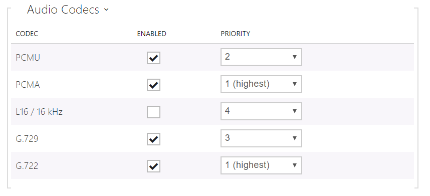
- Audio – audio codec, DTMF and other audio stream parameter transmission settings.
- Video – video codec and SDP codec settings.
- 2N Indoor Units – general parameters and count of identified LAN devices.
SIP 1 and SIP 2
Two SIP accounts can be configured on 2N® Indoor View.

- SIP ACcount Enable – allow the SIP account use for calling. If disallowed, the account cannot be used for making outgoing calls and receiving incoming calls.
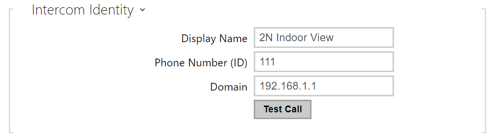 |
- Display Name – set the name to be displayed as CLIP on the called party's phone.
- Phone Number (ID) – set your device phone number (or another unique ID composed of characters and digits). Together with the domain, this number uniquely identifies the device in calls and registration.
- Domain – set the domain name of the service with which the device is registered. Typically, it is equivalent to the SIP Proxy or Registrar address.
- Test Call – display a dialogue window enabling you to make a test call to a selected phone number, see below.
 |
- Authentication ID – enter the alternative user ID for the device authentication. Phone Number (ID) will be used if this parameter is left empty.
- Password – set the device authentication password. If your PBX requires no authentication, the parameter will not be applied.
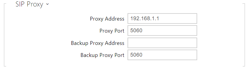 |
- Proxy Address – set the SIP Proxy IP address or domain name.
- Proxy Port – set the SIP Proxy port (typically 5060).
- Backup Proxy Address – set the backup SIP Proxy IP address or domain name. The address is used where the main proxy fails to respond to requests.
- Backup Proxy Port – set the backup SIP Proxy port (typically 5060).
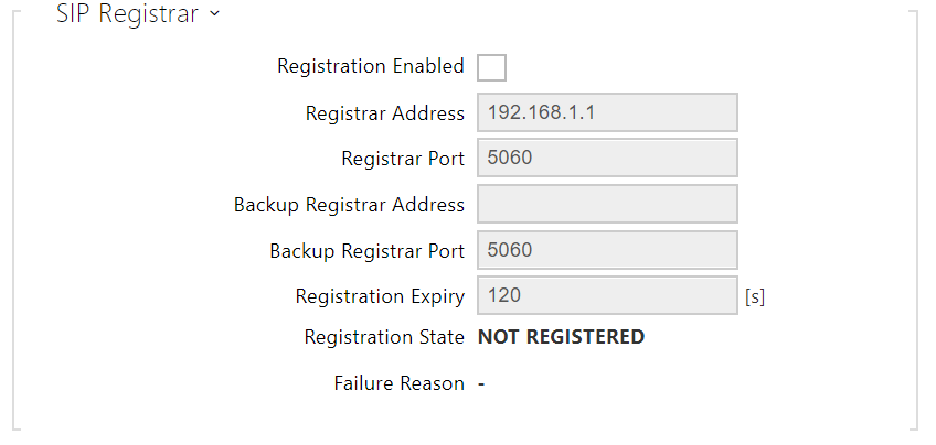 |
- Registration Enabled – enable device registration with the set SIP Registrar.
- Registrar address – set the SIP Registrar IP address or domain name.
- Registrar Port – set the SIP Registrar port (typically 5060).
- Backup Registrar Address – set the backup SIP Registrar IP address or domain name. The address is used where the main registrar fails to respond to requests.
- Backup Registrar Port – set the backup SIP registrar port (typically 5060).
- Registration Expires – set the registration expiry, which affects the network and SIP Registrar load by periodically sent registration requests. The SIP Registrar can alter the value without letting you know.
- Registration State – display the current registration state (Unregistered, Registering..., Registered, Unregistering...).
- Failure Reason – display the reason for the last registration attempt failure: the registrar’s last error reply, e.g. 404 Not Found.
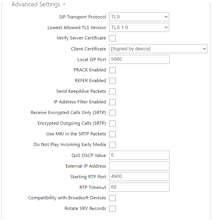 |
- SIP Transport Protocol – set the SIP communication protocol: UDP (default), TCP or TLS.
- Lowest Allowed TLS Version – set the lowest TLS version to be accepted for device connection.
- Verify Server Certificate – verify the SIP server public certificate against the CA certificates uploaded in the device.
- Client Certificate – specify the client certificate and private key used for verifying the intercom’s authority to communicate with the SIP server.
- Local SIP Port – set the local port for thedevice for SIP signaling. A change of this parameter will not be applied until the deviceis restarted. The default value is 5060.
- PRACK Enabled – enable the PRACK method for reliable confirmation of SIP messages with codes 101–199.
- REFER Enabled – enable call forwarding via the REFER method.
- Send Keep Alive Packets – set that the device shall inquire periodically about the state of the called station via SIP OPTIONS requests during the call (used for station failure detection during the call).
- IP Address Filter Enabled – enable the blocking of SIP packet receiving from addresses other than SIP Proxy and SIP Registrar. The primary purpose of the function is to enhance communication security and eliminate unauthorized phone calls.
- Receive encrypted calls only (SRTP) – set that SRTP encrypted calls shall only be received on this account. Unencrypted calls will be rejected. At the same time, TLS is recommended as the SIP transport protocol for higher security.
- Encrypted outgoing calls (SRTP) – set that outgoing calls shall be SRTP encrypted on this account. At the same time, TLS is recommended as the SIP transport protocol for higher security.
- Use MKI in SRTP Packets – enable the use of MKI (Master Key Identifier) if required by the counterparty for master key identification when multiple keys rotate in the SRTP packets.
- Do Not Play Incoming Early Media – disable playing of the incoming audio stream before the call sent by some PBXs or other devices is picked up (early media). A standard local ringtone is played instead.
- QoS DSCP Value – set the SIP packet priority in the network. The set value is sent in the TOS (Type of Service) field in the IP packet header. Enter the value as a decimal number. A change of this parameter will not be applied until the deviceis restarted.
- External IP Address – set the public IP address or router name to which the device is connected. If the device IP address is public, leave this parameter empty.
- Starting RTP Port – set the initial local RTP port in the range of 64 ports used for audio and video transmission. The default value is 4900 (i.e. the range is 4900–4963). The parameter is only set for account 1 but applies to both the SIP accounts.
- RTP Timeout – set the audio stream RTP packet receiving timeout during a call. If this limit is exceeded (RTP packets are not delivered), the call will be terminated by the device. Enter 0 to disable this parameter. The parameter is only set for account 1 but applies to both the SIP accounts.
- Broadsoft Compatibility Mode – set the Broadsoft PBX compatibility mode. Having received re-invite from a PBX in this mode, the intercom replies by repeating the last sent SDP with currently used codecs instead of sending a complete offer.
- Rotate SRV Records – allow SRV record rotation for SIP Proxy and Registrar. This is an alternative method of transition to backup servers in the event of main server failure or unavailability.
Calls
 |
- General Settings – set the call time limit after which the call is automatically terminated. The intercom signals termination with a beep 10 s before the call end. Enter any DTMF character into the call (# on your IP phone, e.g.) to extend the call time.
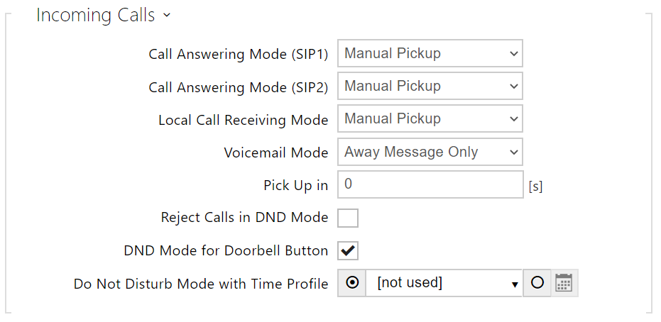 |
- Call Answering Mode (SIP 1, SIP 2) – set the way of receiving incoming calls. The following three options are available:
- Always busy – the device rejects incoming calls.
- Manual answering – the device rings to signal incoming calls and the user can press a keypad button to pick up.
- Automatic – the device picks up incoming calls automatically. You can set the call receiving mode for each SIP account separately.
- Local Call Receiving Mode – set the way of receiving incoming local calls.
- Always busy – the device rejects incoming calls.
- Manual answering – the device rings to signal incoming calls and the user can press a keypad button to pick up.
- Automatic – the device picks up incoming calls automatically. You can set the call receiving mode for each SIP account separately.
- Voicemail Mode – a pre-defined voice message (as set in the User Sounds) is played into the call after a timeout defined in the Pick Up in parameter in the automatic / manual call answering mode if the Only out-of-office message is set. A beep is also played in the Video Voicemail and an up to 20 seconds long call recording starts (audio and video if available) for the calling user to leave a message. If no user message is recorded, a default voice message in one of the seven available languages (as set in the Voice message language) can be used.
- Pick Up in – this parameter is only active when the Automatic pickup mode is enabled. The call is picked up automatically after the preset timeout.
- Reject Calls in DND Mode – if this function is activated, the device reject calls in the Do not Disturb mode. The function can be used for immediate call redirection at absence to a mobile phone call, for example.
- DND Mode for Doorbell Button – if this function is activated, the device shall not ring when the doorbell button is pressed.
- Do Not Disturb Mode with Time Profile – choose one or more time profiles to be applied. Set the time profiles in Directory / Time profiles.
 – select one of the pre-defined profiles or set the time profile for the given element manually.
 |
- Connecting Time Limit – set the maximum outgoing call connection timeout after which the calls are automatically terminated. If the calls are routed to the GSM network via GSM gateways, you are advised to set a value higher than 20 s.
- Ring Time Limit – set the maximum call setup and ringing time in which all outgoing calls are automatically terminated. If the calls are routed to the GSM network via GSM gateways, you are advised to set a value longer than 20 s. Minimum value: 1 s, maximum value: 600 s. Set 0 to disable the time parameter.
 |
- Save Image during Call – if enabled, one or more snapshots are automatically taken from each video call and saved into the call log (depending on the device type and setting). More snapshots can be taken manually during a call in some devices.
- Automatic Image Count – set the count of snapshots that shall be automatically taken during a call and saved into the call log.
Caution
- If the Save Image during Call function is disabled, all the snapshots will be deleted but the call logs will be preserved.
Audio
 |
 |
- In-Band (Audio) – enable the classic method of sending DTMF in the audio band using standardized dual tones.
- RTP (RFC-2833) – enable DTMF sending via the RTP according to RFC-2833.
- SIP INFO (RFC-2976) – enable DTMF sending via SIP INFO messages according to RFC-2976.
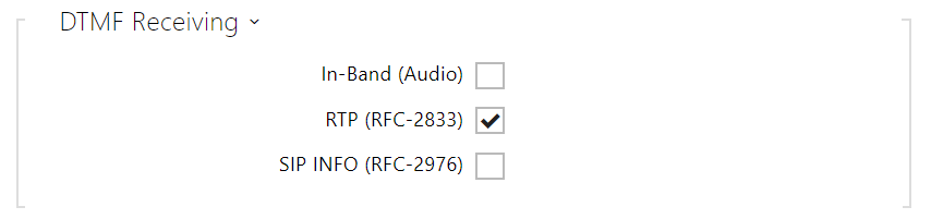
- In-Band (Audio) – enable classic DTMF dual tone receiving in the audio band.
- RTP (RFC-2833) – enable DTMF receiving via RTP according to RFC-2833.
- SIP INFO (RFC-2976) – enable DTMF receiving via SIP INFO messages according to RFC-2976.
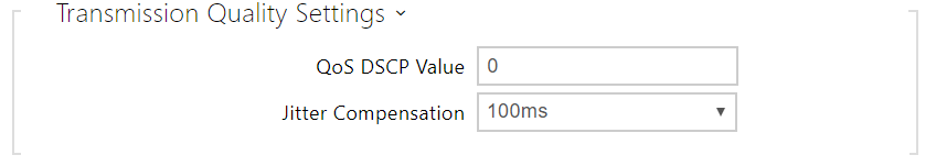 |
- QoS DSCP Value – set the audio RTP packet priority in the network. The set value is sent in the TOS (Type of Service) field in the IP packet header.
- Jitter Compensation – set the buffer length for compensation of interval unevenness in audio packet arrivals. A higher capacity improves the transmission resistance at the cost of a greater sound delay.
Video
 |
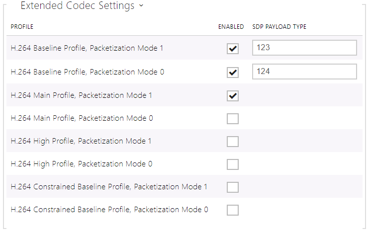 |
- H.264 Baseline Profile, Packetization Mode 1
- H.264 Baseline Profile, Packetization Mode 0
- H.264 Main Profile, Packetization Mode 1
- H.264 Main Profile, Packetization Mode 0
- H.264 High Profile, Packetization Mode 1
- H.264 High Profile, Packetization Mode 0
- H.264 Constrained Baseline Profile, Packetization Mode 1
- H.264 Constrained Baseline Profile, Packetization Mode 0
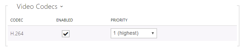
- Enabled – enable the packetization mode and set the payload type for each codec. The payload type can be selected automatically in case it cannot be set manually.
- SDP Payload Type – set the payload type for video codec H.264 (packetization mode 1). Set a value from the range of 96 through 127, or 0 to disable this codec option.
Local Calls
 |
- Enable Local Calls – enable calls between 2N devices in the LAN. With this function off, the other LAN devices cannot locate this device, i.e. cannot call the device in the device:device_ID format.
 |
- Device ID – set the device ID to be displayed in the LAN device list in all the 2N devices in one and the same LAN. You can direct a call to this device by setting the user phone number as device:device_ID in these devices.
 |
- Access Key 1, 2 – set the access key shared by the 2N answering units and intercoms. If the keys in the 2N answering units and the intercoms fail to match, the devices cannot communicate, i.e. the intercom cannot call the 2N answering unit and vice versa.
 |
- Access Key – set the access key shared by the 2N answering units and intercoms. If the keys in the 2N answering units and the intercoms fail to match, the devices cannot communicate, i.e. the intercom cannot call the 2N answering unit and vice versa.
- Multicast Address – set the network multicast address to which the answering unit message shall be sent.
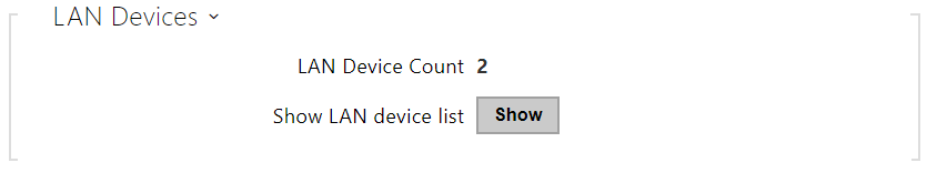 |
- LAN Device Count – display the number of local devices in the network.
- Show LAN device list – display a detailed list of local devices in the network.