4.1 Cabin Switch Connection
The Cabin switch helps you connect up to 4 IP devices located in the lift cabin. It transfers data from the DSL line to 4 Ethernet ports, which support the rate of 10 or 100 Mbps. Two ports provide PoE 802.3af Class 2 (6.49 max) and allow up to 2 devices without power supply to be connected. Typically, they include an emergency communicator, an IP camera and an access system reader.
It is interconnected with the 2N® LiftGate main unit and communicates with it using a 2-wire cable carried in a traveling cable from the lift cabin to the machine room.
The Cabin switch unit is intended for lift cabin installation and suspended using screws or mounted on a DIN rail. There is a DIN rail mounting profile with a lock on the cabin unit back side. Put the upper profile side on the DIN rail and push the cabin unit bottom to fit and lock the cabin unit to the DIN rail. To release the cabin unit from the DIN rail, pull the DIN rail lock a little, using a screwdriver, for example. Now remove the cabin unit from the DIN rail.
1 or 2 48 V power supplies (marked as 1xPS or 2xPS) are available on the main unit for feeding the cabin unit, depending on the device version. Each power supply is able to feed 1 or 2 cabin units, i.e. the total of up to 4 units in the two-supply version. Each cabin unit can be installed in a different lift cabin. The power supply is short circuit resistant and has a resettable electronic fuse.
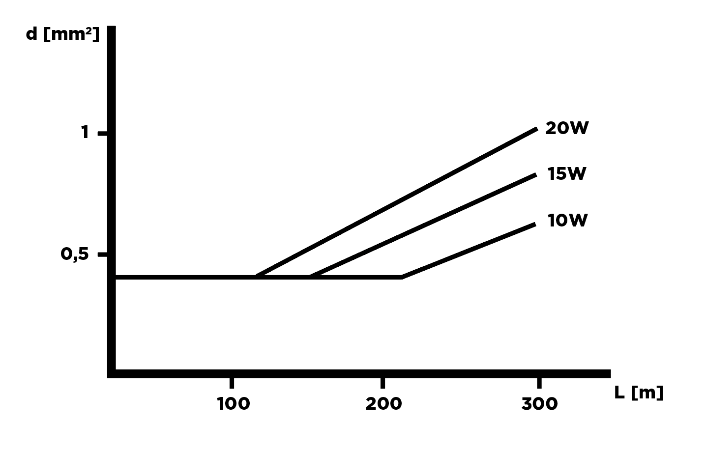
The table and nomogram below include the cabling conditions between the main unit and Cabin switch.
| Length [m] | Minimum cross-section at maximum load [mm2] | Minimum cross-section at just one 2N® LiftGate load [mm2] |
|---|---|---|
| 0–50 | 0.3 | 0.3 |
50–100 | 0.5 | 0.3 |
| 100–200 | 0.75 | 0.3 |
| 200–300 | 1 | 0.3 |
 |
Caution
- The values provided in the table above define under what conditions the main unit is capable of ensuring the operation of the Cabin switch and device connected to it.
- The cabling length and cross-section do not affect the signal strength, the signal depends on the shaft interference.