3.5 GSM
The Virtual ports – GSM menu provides a list of all GSM virtual ports of the PBX. The parameters are divided into logical sections.
Basic
Stack status
This field displays information on the stack and its current status.
Network selection
- Net type selection – select the preferred network for module login. The following options are available:
- Any
- Only GSM
- Prefer GSM
- Only UMTS
- Prefer UMTS
- Roaming enabled – enable roaming for a GSM virtual port.
- Manual network selection – if not checked, the SIM card tries to log into the preferred network automatically. If checked, enter the correct Network code to make the SIM card log into the selected network only. If the selected network is unreachable, the SIM card will not try to log into another network.
- Network code – fill in a 5–digit international network code (e.g. T-mobile CZ=23001, O2 CZ=23002, Vodafone CZ=23003).
- Network name – enter the name of the network as coded in the Network code parameter.
- Cell selection – select the network cell to which the module shall/may log in.
- Off – the cell is selected automatically.
- Prefer selected – the module tries to log in to the cell specified in the parameter below. If unsuccessful, the module tries other available cells.
- Only selected – the module only tries to log in to the cell specified in the parameter below.
- Cell ID – set the network cell identifier for module login.
The following options are available under the right mouse button:
- Known networks – open a dialogue with the list of known networks and their international GSM codes. The networks are arranged according to countries.
- Visible networks – open a dialogue with the list of visible networks in the surroundings. By initiating the search you make your SIM card log out temporarily from the module.
Signal diagnostics
- Signal measuring – enable signal level measuring for a selected carrier.
- Signal monitoring – enable signal level monitoring for a selected carrier. If the signal level drops below the value specified in the Poor signal level parameter, a red exclamation mark appears on the port in the Hardware – Boards menu and a red text is displayed in the upper stack status field. This poor signal status gets changed after the signal level exceeds the value specified in the Good signal level parameter. The interval between the values represents hysteresis.
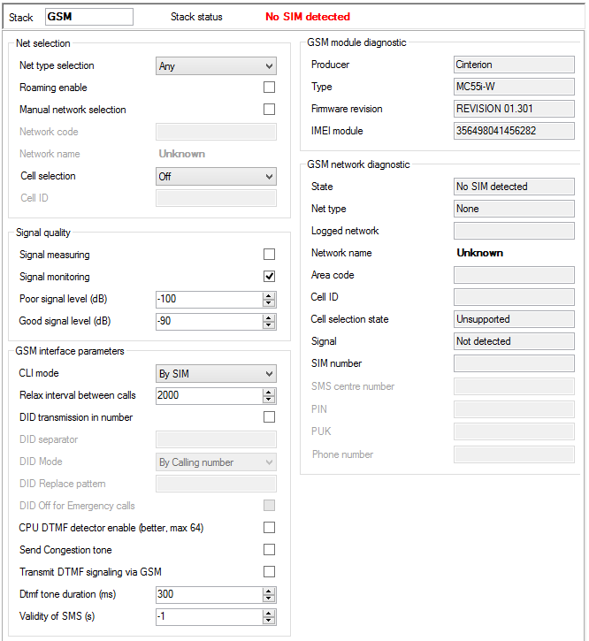 |
Figure: View of GSM Virtual Port Hardware Configuration
GSM interface parameters
- CLI mode – enable CLI restriction for the active SIM card. The following options are available:
- By SIM – the SIM card default setting is respected.
- By calling number – the calling user CLI setting is respected. If CLI is allowed, the SIM card uses CLI too. If not, the SIM card's identification is restricted.
- Presented – SIM CLI is always presented regardless of the SIM card or calling user settings.
- Restricted – SIM CLI is always restricted regardless of the SIM card or calling user settings.
Caution
- This function must be supported by the network provider. Otherwise, calls with suppressed identification are rejected with a corresponding cause.
- Relax interval between calls – determine the idle period between two calls. This parameter only applies to calls going out from the PBX through the GSM carrier, not to incoming calls. During this time all outgoing calls are rejected with cause 34 – no circuit/channel available.
- DID transmission in number – enable a special direct dial-in transmission function within the called number. This function is supported by some networks only.
- DID separator – set a character to separate the called SIM card number and the DID (direct dial-in).
- DID mode – define how to work with the DID. Select one of the following options:
- By calling number – if the calling user has CLIR, the calling number is not displayed in the DID (777982494#). If not, the calling number is displayed behind the DID separator (777982494#274).
- Always presented – CLI is always presented in the DID regardless of the CLI setting (777982494#274).
- Restricted DID replace – the mode is similar to the By calling number mode; the only difference being that, in the case of CLIR enable, the identifier specified in the DID replace pattern parameter is displayed behind the DID separator instead of the CLI (e.g. 777982494#888).
- DID replace pattern – specify the DID to be used as the caller's identification in the case of CLIR.
- DID off for emergency calls – disable the use of DID for specified emergency calls while the PBX is in one of the modes as described in detail in the .3.5 Přenašeč GSM v4.4 menu.
- CPU DTMF detector enable – disable/enable DTMF detection using a board detector in order to save internal PBX detectors.
- Send congestion tone – if this item is selected and the port requires tones, the PBX generates the congestion tone to the other party after the call end until the port receives the Release message or the 30s timeout expires. If this item is not selected, the channel is closed practically on the telephone hang-up. If the port requires no tone, the channel is closed immediately too.
- Transmit DTMF signaling via GSM – enable sending of DTMF signalling via GSM instead of a voice channel for better detection by the counterparty. The function is available for the GSM card with MC55 modules only – Part No. 1011708E.
- DTMF tone duration [ms] – define the DTMF tone duration.
- Validity of SMS [s] – set validity of the SMS to be sent to the provider's network. Always round the value up. The steps are as follows: 5 minutes for up to 720 minut (12 hours), 30 minutes for 12 to 24 hours, 1 day for 1 to 30 days and 1 week for 4 to 63 weeks.
GSM modul diagnostic
- Producer – provides information on the board manufacturer.
- Type – provides information on the board type.
- Firmware revision – the software revision of the firmware uploaded into the board.
- Module IMEI – shows the detected IMEI code.
GSM network diagnostic
- State – shows the current port state for detection of network login problems if any. For example, PIN REQUESTED means that the SIM card requires the PIN code to log in. To log in successfully, you either enter the PIN or disable PIN requesting by the SIM card.
- Net type – shows the network type to which the module is logged at the moment.
- Logged network – shows the international code of the network to which the SIM card is logged at the moment.
- Network name – shows the name of the network into which the SIM card is logged at the moment.
- Area code – displays the code of the area to which the SIM card is logged at the moment.
- Cell ID – identifies the cell to which the SIM card is logged at the moment.
- Cell selection state – informs whether the given module supports manual cell selection.
- Signal – shows the current signal level (if activated). A low signal level may result in logout or call failure due to a high error rate.
- SIM number – shows the SIM card code detected.
- SMS centre number – fill in this parameter to enable SMS sending. In GSM networks, SMSs are not routed directly to the final destination, but through the provider's SMS centre. This is useful where an SMS cannot be delivered immediately (e.g. due to target phone unavailability). The SMS centre tries to deliver this message cyclically for a preset SMS validity time. This parameter is mostly automatically detected on the SIM card (preset by the provider). If not, fill it in manually.
- PIN – enter the PIN code if it is required by the SIM card and has not been entered in the SIM – SIM cards menu for this SIM card.
- PUK – enter the PUK code if it is required by the SIM card and has not been entered in the SIM – SIM cards menu for this SIM card.
- Phone number – this field is for information only. You can enter your SIM card telephone number for easier orientation. This parameter has no function.
Expert
AT commands
You can add AT commands here to set the module properties. These AT commands are executed upon every PBX restart or GSM/UMTS card restart. Use the arrows in the right-hand part of the section to specify the sequence of the commands. The Timeout column sets the time during which the answer to the command entered is awaited. The Result columns includes a brief statement on whether or not the command was successful. For specific answers see the Answers for selected section.
Answers for selected
Here find an answer to the AT command selected in the left part of the screen.
Net code locks
Use a special licence to restrict a module to a specific network. This restriction is permanent. Use a special licence again to unlock the status. The lock supports up to 8 networks.
Lock mode:
- Unused – the lock is not activated.
- First enable – the module is locked for the first network to which it logs in.
- Enable – the module may log in to the selected networks only.
- Disable – the module may log in to all networks except for those selected in the Net code section.
SIM num locks
Use a special licence to restrict a module to a specific SIM card. This restriction is permanent. Use a special licence again to unlock the status. The lock supports up to 4 SIM cards.
Lock mode:
- Unused – the lock is not activated.
- First enable – the module is locked for the first SIM card inserted.
- Enable – the selected SIM cards may log in to the module only.
- Disable – all SIM cards may log in to the module except for those selected in the SIM num section.
Audio parameters
Here set the audio profile for various Siemens MC55/MC55i GSM module versions.
- MC55 Audio Profile – select the module version.
- Tx gain – set the gain of the audio signal to be transmitted – not implemented yet.
- Rx gain – set the gain of the audio signal to be received – not implemented yet.
USSD
USSD commands
This section helps you enter the USSD commands (codes) for prepaid SIM card recharging or credit info obtaining, for example. Click New to enter the required command and Repeat to repeat the last-entered command. Click Cancel to abort the currently executed command. View the information on the USSD command result in the Reply window.
- Network name – display the name of the network to which the SIM card is logged in at the moment.
- Command – display the last-entered USSD command.
- State – provides information on the command processing.