3.4 CO
The CO virtual port is an analogue virtual port for connection of a CO (central exchange) analogue line. Since it has only a DTMF transmitter, it is unable to detect the DTMF. Therefore, route an incoming call directly to the final destination, or assign the DISA function to the virtual port to detect the DTMF symbols and route the call to the required destination. The parameters are divided into logical sections.
Basic
Stack status
This field displays information on the stack and its current status. With a CO virtual port you can see the following statuses:
- null
- config
- on_hook
- off_hook
- error_stop
- error_start_req
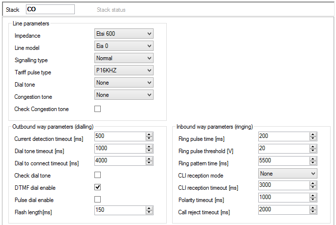 |
Figure: View of CO Virtual Port Hardware Configuration
Line parameters
- Impedance – determines the impedance of the hybrid coil according to preset models (User, ETSI 600, Germany and Real 600).
- Line model – determines further hybrid coil parameters according to preset models EIA0 to EIA7 (e.g. EIA0 represents a 100m long line model).
- Signalling type – shows the type of active state signalling. Choose one of the Reverse polarity, Tariff pulse or Simple options.
- Tariff pulse type – defines the tariff pulse sending source. Choose 12 kHz, 16 kHz or none.
- Dial tone
- Congestion tone – select the congestion tone mask for testing purposes. The setting is available if the Check Congestion tone parametr is ticked off.
- Check congestion tone – tick off this option to test the presence of the congestion tone. If the congestion tone is detected, the port passes to the On hook state.
Outbound way parameters (from PBX)
- Current detection timeout [ms] – set the time for current detection on the picked-up carrier. If no current is detected within this timeout, a failure is reported.
- Dial tone timeout [ms] – set the waiting time for dialling numbers to the carrier. Select the Check dial tone option to test the dial tone presence during this time.
- Dial to connect timeout [ms] – set the maximum delay time for CO line dialling. Time monitoring is renewed after every digit entered. If no digit is detected within this timeout, the connection will be regarded as terminated and a new connection attempt will be made.
- Check dial tone – enable dial tone testing on the carrier for a period of time set in the Dial tone wait timeout parameter.
- DTMF dial enabled – enable DTMF dialling via the port.
- Pulse dial enabled – enable pulse dialling via the port.
- FLASH length [ms] – set the maximum time of the FLASH transmitted from a local phone to the PBX. The default value is 150 ms and the minimum value is 80 ms.
Inbound way parameters (to PBX)
- Ring pulse time [ms] – this parameter sets the minimum time of the ring signal presence needed for ring detection. If the ring time is shorter than the preset value, ringing will be ignored.
- Ring pulse treshold [V] – this parameter sets the minimum ring voltage level needed for ring detection. If the ring voltage level is lower than the preset value, ringing will be ignored.
- Ring pattern time [ms] – this parameter sets the minimum period of time for alerting detection.
- CLI reception mode – define the preferred CLIP (Calling Line Identification Presentation) reception type. Choose DTMF, FSK or none.
- CLI reception timeout [ms] – set the CLI detection timeout as counted from the end of the first ring. This option is active only if the DTMF or FSK reception mode has been selected.
- Polarity timeout [ms] – set the reverse polarity timeout. This option is active only if the Reverse polarity item has been selected for this virtual port.
- Call reject timeout [ms] – if the PBX needs to reject an incoming CO call, it has to pick up and hang up. Use this parameter to define the timeout for this action. If the action is too short, the other party will not recognise termination.
Expert
Chipset
- Chipset Type – this parameter determines the type of the chipset used. The SILABS_SI350 chipset is only supported at present.
- Chipset Config – activate one of the chipset configurations created.
- New config – create a new configuration for the selected chipset type.
Specific Chipset configuration
- Name – set the chipset type whose configuration is being set in the section.
Caution
- Do not change the above mentioned parameters unless absolutely necessary.
- DCTerm – set the DC termination parameters (ringing voltage, minimum current, impedance). Hexadecimal values are used.
- DAA Ctrl 5 – set further parameters for analogue line matching (on/off-hook rate, low pass filter). Hexadecimal values are used.
- ACIM – set the proper impedance. Hexadecimal values are used.
- Tx Gain – set the transmit gain.
- Rx Gain – set the receive gain.
The table below includes the ACIM settings including meanings.
ACIM [3:0] | Set | AC termination |
|---|---|---|
0000 | 00 | 600 Ohm |
0001 | 01 | 900 Ohm |
0010 | 02 | 270 Ohm + (750 Ohm || 150 nF) and 275 Ohm + (780 Ohm || 150 nF) |
0011 | 03 | 220 Ohm + (820 Ohm || 120 nF) and 220 Ohm + (820 Ohm || 115 nF) |
0100 | 04 | 370 Ohm + (620 Ohm || 310 nF) |
0101 | 05 | 320 Ohm + (1050 Ohm || 230 nF) |
0110 | 06 | 370 Ohm + (820 Ohm || 110 nF) |
0111 | 07 | 275 Ohm + (780 Ohm || 150 nF) |
1000 | 08 | 120 Ohm + (820 Ohm || 110 nF) |
1001 | 09 | 350 Ohm + (1000 Ohm || 210 nF) |
1010 | 0A | 0 Ohm + (900 Ohm || 30 nF) |
1011 | 0B | 600 Ohm + 2.16 µF |
1100 | 0C | 900 Ohm + 1 µF |
1101 | 0D | 900 Ohm + 2.16 µF |
1110 | 0E | 600 Ohm + 1 µF |
1111 | 0F | Global complex impedance |