3.1 BRI a PRI
BRI
Refer to the 2.2 Boards subsection for the meaning of the virtual port.
BRI virtual ports are assigned to physical ISDN ports for the Basic Rate Interface. For the hardware configuration of BRI virtual ports refer to the Virtual ports – BRI/PRI menu in the Stack tab. A list of all BRI virtual ports is displayed on the left and a window for the port parameter setting is available on the right. The configuration parameters are divided into logical parts.
Stack status
This field displays information on the stack and its current status including information on the L1 or L2 states, higher error rates or loss of synchronisation.
Digital interface parameters
- Interface type – cannot be selected, only shows the type of interface including bit rate information.
- Interface mode – switch between the NT (Network Termination) and TE (Terminal Equipment) modes. Some basic unit positions can only be used in the NT mode. Specifically, they are basic unit board positions 6, 9 and 12 if you follow addressing as described in 2.2 Boards. A correct function requires a software-hardware matching and a proper jumper setting for each board port. Figure below may serve as a guide.
- Bus mode – switch between the MPT (point-to-multipoint) and PTP (point-to-point) modes. In the MPT mode you can connect up to eight terminals to one physical port. The PTP mode is mainly used for cross-connecting lines (trunks) between PBXs or for one terminal connection.
- Enabled channels – activate the B–channels. If no channel is checked off, you cannot use this port for communication (it behaves as if busy).
- Deactivate L1 at relax – deactivate the L1 layer on an inactive interface. The PBX automatically deactivates the layer after a timeout as defined in the Deactivation timeout item. Any incoming call automatically reactivates this layer.
- Keep L1 active – make the PBX keep L1 active on this interface without any incoming call. This option cannot be combined with the Deactivate L1 at relax option.
- Inactive L1 as error – activate a caution about the first layer being inactive. This is indicated by a red exclamation mark on the port in the Hardware – Boards menu and a red text in the upper stack status field. This option may not combined with the Deactivate L1 at relax option.
- Set SLIP – select Nonsynchronous as error to enable acceptable SLIP range parameters. Use this option in the TE mode only. If the SLIP rate gets over the upper level, a red exclamation mark appears on the port in the Hardware – Boards menu and a red text is displayed in the upper stack status field. This error status gets changed after the SLIP rate falls below the lower level. The interval between these two values represents hysteresis.
- Settings for BER – select BER as error to enable acceptable interface error parameters. If the BER rate gets over the upper level, a red exclamation mark appears on the port in the Hardware – Boards menu and a red text is displayed in the upper stack status field. This error status gets changed after the BER value falls below the lower level. The interval between these two values represents hysteresis. The BER values are entered in an exponential format (e.g. 3e–5 means 3 errors in 100,000 bits). In practice, the BER may occur on a virtual port close after the cable connection. In that case, this is not an error if the BER disappears in a few minutes.
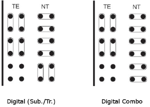 |
View of ISDN BRI Board Jumper Configuration (Thick Line Represents Board Front)
Specific interface parameters
- Multiframe – is the first layer parameter of the So bus. For details refer to recommendation I.430.
- Extended bus – activate an extended bus. With just one terminal and proper terminating impedance you can extend the PBX–terminal distance up to 1,000 metres. This parameter can be set for an NT port only.
- Priority 10 – is the first layer parameter of the So bus. This parameter can be set for a TE port only.
DSS1 protocol parameters
- Reverse NT/TE mode – this option refers to L3 signalling only. Check this option to make a TE port behave as an NT port (and vice versa).
- Do not send time at NT – disable sending of the connection date and time information within the CONNECT message from an NT port to a TE port. Available for NT ports only.
- Ignore unset explicit channel – enable call establishment without an explicitly set B–channel.
- Always select B–channel – disable sending the channel identification information within the SETUP message together with channel signalling. Available for TE ports only.
- Disconnect L2 if there is no call – disconnect the L2 layer on a inactive interface. The PBX automatically disconnects the layer after a timeout. An incoming call automatically reconnects the layer.
- Keep L2 connected – make the PBX to keep L2 connected on this interface without any incoming call. This option may not be combined with the Disconnect L2 if no call option.
- Disconnected L2 as error – activate a caution about the second layer being disconnected. This fact is indicated by a red exclamation mark on the port in the Hardware – Boards menu and a red text in the upper stack status field. This option may not be combined with the Disconnect L2 if no call option.
- Outgoing numbering plan – this option allow to set up numbering plan type for called number within the SETUP message.
- Terminals – is active for virtual MPT NT ports. Enter all connected ISDN terminals including their MSN numbers. Assign a extension to these terminals using the Extensions tab. The terminal shall then identify itself as the selected extension within the PBX.
Caution
- 2N® NetStar allows only the calls encoded with G.711 A–law to be processed on the ISDN interface (i.e. to be sent to interfaces other than ISDN). G.711 µ–law encoded incoming calls can only be sent between the ISDN interfaces via the PBX.
Digital interface diagnostic
- Line state – the parameter cannot be set. It only shows the state of the first interface layer.
- Number of SLIPs per minute – set the count of slips. A slip is caused by different clocks of the PBX and the active terminal. This value is updated every 6 seconds and represents a weighted average per minute.
- Bit error rate per second – the BER parameter gives a count of incorrectly transferred bits during transmission. The value is updated every 6 seconds and represents a weighted average per minute.
If the SNMP port supervision is used, enable some or all of the following parameters: Inactive L1 as error, Disconnected L2 as error, Nonsynchronous L1 as error, BER as error. If not, the port error will not be detected and the PBX will be unable to send a warning.
Expert tab
- OUT parameters (PBX out)
- IN parameters (PBX in)
PRI
Refer to the 2.2 Boards subsection for the meaning of the virtual port.
PRI virtual ports are assigned to physical ISDN ports for the Primary Rate Interface. For the hardware configuration of the PRI virtual ports refer to the Virtual ports – BRI/PRI menu in the Stack tab. A list of all available PRI virtual ports is displayed on the left and a window for the port parameter settings is on the right. The configuration parameters are divided into logical parts.
Stack status
This field displays information on the stack and its current status including information on the L1 or L2 states, higher error rates or loss of synchronisation.
Digital interface parameters
- Interface type – the parameter cannot be configured. It only shows the type of interface including bit rate information.
- Interface mode – switch between the NT (Network Termination) and TE (Terminal Equipment) modes. A correct function requires a software-hardware matching and a proper jumper setting for each ISDN board port. Figure below may serve as a guide.
- Enabled channels – activate the B–channels. If no channel is checked off, you cannot use this port for communication or data transmission (it behaves as if busy). B–channels 0 and 16 cannot be used for call or data transmission under normal circumstances since they are blank. In PCMs of the 1st order are used for frame synchronisation and signalling transmission.
- Deactivate L1 at relax – deactivate the L1 layer on an inactive interface. The PBX automatically deactivates the layer after a timeout as defined in the Deactivation timeout item. Any incoming call automatically reactivates this layer.
- Keep L1 active – make the PBX keep L1 active on this interface without any incoming call. This option cannot be combined with the Deactivate L1 at relax option.
- Inactive L1 as error – activate a caution about the first layer being inactive. This is indicated by a red exclamation mark on the port in the Hardware – Boards menu and a red text in the upper stack status field. This option may not combined with the Deactivate L1 at relax option.
- Settings for SLIP – select Nonsynchronous as error to enable acceptable SLIP range parameters. Use this option in the TE mode only. If the SLIP rate gets over the upper level, a red exclamation mark appears on the port in the Hardware – Boards menu and a red text is displayed in the upper stack status field. This error status gets changed after the SLIP rate falls below the lower level. The interval between these two values represents hysteresis.
- Settings for BER – select BER as error to enable acceptable BER range parameters. If the BER rate gets over the upper level, a red exclamation mark appears on the port in the Hardware – Boards menu and a red text is displayed in the upper stack status field. This error status gets changed after the BER rate value falls below the lower level. The interval between these two values represents hysteresis. The BER values are entered in an exponential format (e.g. 3e–5 means 3 errors in 100,000 bits). In practice, the BER may occur on a virtual port close after the cable connection. In that case, this is not an error if the BER disappears in a few minutes.
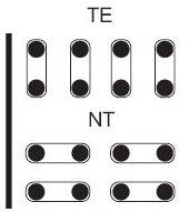 |
View of ISDN PRI Board Jumper Configuration (Thick Line Represents Board Front)
Specific interface parameters
- Prefer CRC – enable preferring communication with the Cyclic Redundancy Check. In this mode, the PBX tries to establish connection with the CRC at first and, having failed, attempts to establish connection without the CRC.
- Long haul – activate an extended bus called the Long Haul. With just one terminal and holding impedance, you can extend the distance up to 1,000 metres. This parameter can be set only on an NT port.
DSS1 protocol parameters
- Reverse mode NT/TE – this option refers to L3 signalling only. Check this option to make a TE port behave as an NT port (and vice versa).
- Do not send time at NT – disable sending of the connection date and time information within the CONNECT message from an NT port to a TE port. Available for NT ports only.
- Ignore unset explicit channel – enable call establishment without an explicitly set B–channel.
- Always select B–channel – disable sending the Channel identification information within the SETUP message with channel signalling. Available for TE ports only.
- Disconnect L2 if no call – disconnect the L2 layer on an inactive interface. The PBX automatically disconnects the layer after a timeout. An incoming call automatically reconnects the layer.
- Keep L2 connected – make the PBX keep the L2 layer connected on this interface without any incoming call. This option may not be combined with the Disconnect L2 if no call option.
- Disconnected L2 as error – activate a caution about the second layer being disconnected. This fact is indicated by a red exclamation mark on the port in the Hardware – Boards menu and a red text in the upper stack status field. This option may not be combined with the Disconnect L2 if no call option.
- Outgoing numbering plan – this option allow to set up numbering plan type for called number within the SETUP message.
- Terminals – not applied for PRI ports.
Caution
- 2N® NetStar allows only the calls encoded with G.711 A–law to be processed on the ISDN interface (i.e. to be sent to interfaces other than ISDN). G.711 µ–law encoded incoming calls can only be sent between the ISDN interfaces via the PBX.
Digital interface diagnostic
- Line state – the parameter cannot be set. It only shows the state of the first interface layer.
- Number of SLIPs per minute – set the count of slips. A slip is caused by different clocks of the PBX and the active terminal. This value is updated every 6 seconds and represents a weighted average per minute.
- Bit error rate per second – the BER parameter gives a count of incorrectly transferred bits during transmission. The value is updated every 6 seconds and represents a weighted average per minute.
If the SNMP port supervision is used, enable some or all of the following parameters: Inactive L1 as error, Disconnected L2 as error, Nonsynchronous L1 as error, BER as error. If not, the port error will not be detected and the PBX will be unable to send a warning.
Expert tab
- OUT parameters (PBX out)
- IN parameters (PBX in)