2.2 Boards
HW Arrangement
Unfolding the HW – Rack menu you can see the rack fitting as shown in the figure below.
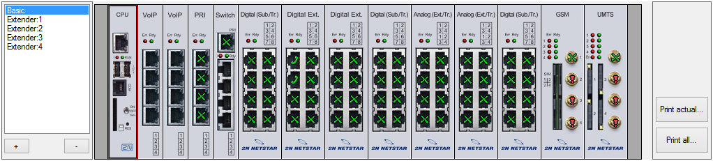 |
| Figure: View of PBX Basic Unit Panel |
- Do not remove or insert the board from the PBX without prior PBX switching off or into the service mode to avoid the PBX damage.
Use the list on the left-hand side of the PBX to switch between the basic unit and extender views. Click on the right-hand mouse button in the basic unit or extender view to display the following options:
- Add board – click on an empty (no-board) PBX position to use this option. Add a board that has been detected by the PBX (using the Detected option) or a board from the list of supported boards for this position.
- Remove board – remove a selected board. If virtual ports or resources have been assigned to the board, you will be asked whether they should be removed or retained.
- Migrate virtual port/resource – use only if the context menu has been displayed on a port to initiate a virtual port substitution dialogue.
- Synchronise with detected – synchronise the current unit or extender with the detected PBX boards. Before a board is removed from the current configuration, you are asked to confirm the removal.
- Expert menu – access the advanced unit, board or port configuration functions. For details see later.
Note
- Let us explain the terms "virtual port" and "physical port" and their difference for convenience. Basically, a virtual port is used for software setting of basic properties of a physical port. The advantage of this approach is the fact that the defined set of properties is attributed to a physical port only if the virtual port is assigned to it. Thus, you can esily move virtual ports between physical ports and change their functions as necessary
- Expert menu – Virtual port
- Assign virtual port – assign an existing virtual port to a physical port. Select a virtual port from the list of existing ports.
- Create virtual port – use this option only for physical ports without any assigned virtual port. The new virtual port is automatically assigned to this physical port.
- Remove virtual port – remove a virtual port from a selected physical port without deleting it. This virtual port can be used later including all settings (routing, assigned extensions, etc.). Rename the virtual port from XXX to UnassignedXXX.
- Delete virtual porte – remove and delete a virtual port once forever. You will not be able to use this port any more.
- Regenerate name – rename a selected virtual port according to its physical port.
- Expert menu – Board and Case
- Create virtual ports/resources – create virtual ports (resources) for all of those physical board or unit ports at once that have not been assigned a virtual port.
- Remove virtual ports/resources – remove all virtual board or unit ports at once without deleting them. These ports can be used later including their settings. Rename these virtual ports from XXX to UnassignedXXX.
- Delete virtual ports/resources – delete all virtual board or unit ports once forever. You will not be able to use this port any longer.
- Regenerate unchanged names – change all unchanged names of the virtual board or unit ports according to their physical ports.
Regenerate all names – change the names of all virtual board or unit ports according to their physical ports.
Board
The figure below shows all possible signalling statuses on the board ports.
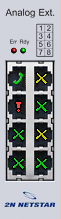 |
Figure: View of Available Analog Board Signalling Statuses
- Earphone
- Cross
- Green – signals a physical port with an assigned virtual port.
- Yellow – signals a physical port with an assigned virtual port and active call (or call establishment).
- Green – signals a physical port with an assigned virtual port and assigned extension.
- Yellow – signals a physical port with an assigned virtual port, assigned extension and active call (or call establishment).
- Exclamation mark
- Yellow – signals a physical port without any assigned virtual port or physical port without detected status.
- Red – signals a hardware error, e.g. a low signal level for a GSM, GSM port without SIM card, ISDN virtual port with deactivated L1 or L2 (adjustable), etc.
PBX Hardware Configuration Printing
Use the buttons to the right of the main unit image or extender to print out the current hardware configuration of the PBX. Click one of the buttons to display a print setting window. Click Print to display a preview and click the button in the left-hand upper corner of the window to print it out. The buttons in the right-hand upper corner help you display the preview on the extenders connected.
- Print actual view – print the view selected by the buttons to the left of the CPU (main unit or extender).
- Print all – print both the main unit and the extenders.
Boards
A two-part Boards tag is available under the PBX view. The upper part shows basic information on the selected board. The parameters mean the following:
- Position – gives the board position number in the case as described below.
- Type – gives the type of the board to be configured.
- Enabled – disables the selected board. This option is useful, for example, while changing SIM cards without switching off the PBX.
- State – provides the current board status including information on a mismatch of the board to be configured with the detected one.
- Detected – shows the parameters of the board detected.
- Type – type of the board detected on a selected position.
- Serial number – serial number of the board detected on a selected position.
- MAC address – MAC address of the board detected on a selected position.
A window showing the list of physical ports of the selected board is displayed under the above-mentioned part. The meaning of each list column is explained in the 2.4 Board and Port List chapter.
Tab Virtual port
The Virtual port tag helps you configure your virtual ports easily. You can set all parameters of the selected virtual ports and simultaneously see the panel layout. Use the Virtual port tag for an easy configuration of virtual ports. The tag includes all configuration settings for the selected virtual port while keeping the PBX view. Click on a card or its port to display the port assignment to a virtual port type in the left section of the screen. Use the drag&drop function to move a virtual port to another type. If you select the CPU card, all the virtual ports that use the card's LAN interface are displayed. Thus, you will see the SIP Proxy and SIP Gateway virtual ports as well as the SMTP and SMTPD virtual ports.
For details on the setting options associated with the parameters in the right-hand section of the tag refer to the User Manual chapters dedicated to particular virtual ports (especially 3. Virtual Ports).
Addressing
The position of each board is specified in the R : C : B format and the position of a port in the R : C : B : P format. The characters have the following meanings:
- R – rack number;
- C – rack unit number;
- B – unit board number;
- P – board port number.
Currently, R takes up the value of 0 and C ranges from 1 to 5, the basic unit being 1, the first extender 2 and so on up to the fourth extender with number 5. The board positions (B) in the basic unit are numbered 1 to 14 from the left. The extender positions are numbered similarly, from 1 to 12. The first basic unit and extender position is always reserved for the CPU board. The 1x/2x/4x ISDN PRI (with or without Zarlink) or Surf Ethernet boards can be mounted into positions 0:1:2 to 0:1:4 only. The position 0:1:5 is reserved for the Switch board, which contains the digital switching array.