1.3 PBX Activation
What You Need
To activate and configure 2N® NetStar you need the 2N® NetStar system, a computer running the supported Windows version, a keyboard and a mouse. The PC and 2N® NetStar PBX have to be interconnected in a LAN. Furthermore, it is necessary to display the redirected standard PBX input and output on your PC console. To do this, you need a six-wire, crossed cable with a six-pin RJ–12 connector on one end and a serial connector on the other. This cable is supplied as standard equipment. You can use a 'Tera Term Pro' console or any other functional console. You can also work in the HyperTerminal mode, but longer lines are interlaced.
Step 1: IP Address Setting
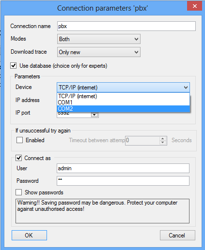
Prior to starting configuration you need to set up the PBX IP address to establish network communication between the system and the computer. To do this, you can use a serial console or the default IP address 192.168.100.100. The 2N® NetStar – PC communication can be on-line or off-line. To configure the console use the table below.
Speed | 115200 |
|---|---|
Bits | 8 |
Parity | None |
Stop bits | 1 |
Flow control | None |
If necessary, a serial port or modem may be used for PBX connection through the configuration tool, yet at a considerably lower bit rate.
 |
Step 2: Hardware Activation
After the first connection to the selected PBX according to the Connection to PBX section, a configuration wizard is displayed as shown in figure below. This wizard is displayed only if the PBX has a new empty database (has not been preconfigured according to your demands).
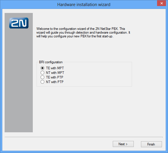 |
Figure: View of Hardware Configuration Wizard Dialogue
When the wizard gets displayed, you can define the basic configuration settings of the virtual BRI ports. If you are not sure, you can push the Next button to proceed to the next configuration step because these settings may be changed any time later. Once you do that, the configuration tool (together with the PBX) starts to detect the hardware as shown in figure below.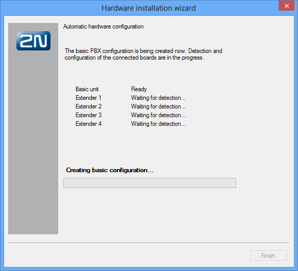 |
Figure: View of Wizard Hardware Detection Operations
The boards are detected both in the basic unit and extenders. Once some hardware is detected, activation takes place, which means that virtual ports are assigned to all the boards detected (except for VoIP boards). The terminals connected are detected in the last stage of the wizard hardware configuration. This should make the PBX ready for further configuration, which is signalled by green board LEDs. The GSM board is the only board without LED indicators and so its ready status is signalled by the port LEDs. The current firmware version is loaded into the PBX after the first start-up or every firmware upgrade and may cause a short delay in the GSM board activation.
Step 3: Localisation Setting
Localisation setting is another important step of the 2N® NetStar configuration. In this step you can define the parameters shown in figure below and described in detail in the 6.3 Localisation subsection. In addition, you can add a language package of your own including texts and progress tones. Two language packages – Czech and English – are available in the PBX by default.
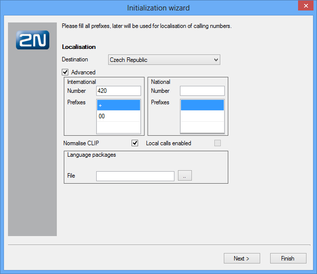 |
Figure: View of Wizard Localisation Setting Operations
Step 4: Time Setting
In this step, the wizard helps you set time, date and time zone. And also define the NTP server for automatic time synchronisation.
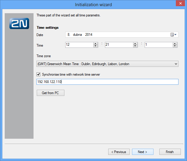 |
Figure: View of Configuration Wizard Time Setting
Step 5: PBX Function Selection
In this step, choose one of the PBX modes. The setting is not final, it just defines the wizard's next configuration steps. The following options are available:
- Private branch exchange
- Virtual branch exchange
- GSM gateway
- Hotel
The offer of settings depends on the PBX mode selected. The lowest number of settings are available in the GSM gateway, where some steps are omitted and configuration starts as late as the SMTP. The settings are identical for the other modes except for step 1, which is always adapted to the particular version. The following steps are available in the Private branch exchange.
Step 6: Creation of Groups, Users and Extensions
In this step, the configuration wizard enables an automatic creation of a group and its users and extensions. There are three types of extensions to be generated – analog, SIP and Cornet extensions. Analog extensions are used for the ASL virtual ports. SIP extensions are used for connecting SIP–supporting VoIP terminals and are assigned to the SIP proxy terminals. Cornet extensions are used for the StarPoint key (system) phones connected to the Cornet virtual ports. You can define the first extension number and count of extensions for each group (every other extension has a number increased by one). The extensions are then assigned to ports according to their types (if possible).
If you do not want to create extensions automatically, you can import the company structure from a pre-prepared file in the xml or csv format. In this way you can create a relatively complex company structure including user logins and multiple user extensions.
Three functions are added to this section, the first two of which are used for re-launching of the wizard.
- Add new and remove deleted – compare the existing structure of extensions with the selected file. New extensions are added and those which are present in the PBX yet undefined in the file are removed.
- Add new only – compare the existing structure of extensions with the selected file and new extensions are added only. Undefined extensions are retained in the configuration.
- Assign ports randomly – enable random assignment of extensions to ports.
If you neither want to automatically create extensions nor intend to import the company structure, you can click Next and select Don't create anything to proceed to the next step.
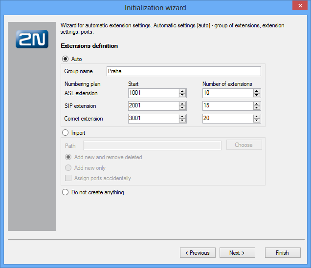 |
Figure: View of Wizard Extension Creation or Intra-Plant Structure Import
Step 7: Settings for Assistant
This configuration step includes just two functions with the following meanings:
- Launch web server – launch the internal PBX web server, to which you can log in by entering the CPU IP address from your web browser.
- Generate default logins – generate logins for the users created in the preceding step. With them, you can log in to the web server as a user.
Step 8: SIP Domain Setting
This step helps you define a specific SIP domain. If this option is not selected, the CPU IP address is used as the domain.
Step 9: SMTP Setting
Within this step you can define the SMTP server to be used by the PBX. Port 25 and the CPU Ethernet interface are set automatically for the SMTP. No security is used by default.
Step 10: Creation of Routers
The wizard's last step is creating PBX routers. Routers are used for call/SMS routing from one PBX port to another. The wizard offers several default sets of routers, which are sufficient for your basic call routing. For special routing demands, reconfigure the routers and add new ones. All new routers are automatically filled with services, extensions and users and linked with each other.
Click Add routers for VoiceMail to create the routers and DISA objects for user VoiceMail.
Step 11: Data Saving
Changes are not automatically stored into the PBX during the wizard process. To save the changes, click the Save button after completing the wizard. To cancel all new settings, push the Undo button.