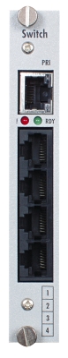
2.6 SWITCH card
The SWITCH card is an inseparable part of the basic module.
- It can be supplied in two HW alternatives.
Switch X without the possibility of extension modules connection, standardly supplied as a part of the Basic Module Lite version.
Switch with the possibility of the connection of up to 4 extension modules.
- Both card versions are always equipped with 1 PRI interface and basic connection field that is in charge of the connection of call in the entire system.
- It is only used in the basic module and is always installed in the position with 5 as the HW address.
 |
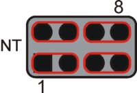
The set-up of the Jumpers on the board determines the NT or TE port type
- NT port set-up
- For NT port the pins 1–3, 2–4, 5–7, 6–8 should be connected
 |
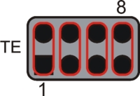
- TE port set-up
- For TE port the pins 1–2, 3–4, 5–6, 7–8 should be connected.
 |
Extender connection interface
- Interface type – proprietary
- Connection – RJ-45 (8x8)
- Maximum connection length – 160cm (wiring supplied as a part of the extender package)
- Total interface capacity – 124 calls
- Ratio capacity of the interface – 4x 31 calls
- Maximum capacity per 1 extender 88 calls
1x PRI interface
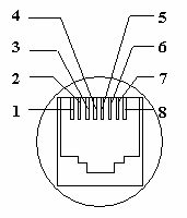 |
- Interface type – S0 without power supply / NT–TE
- Protocol – DSS1 – EURO ISDN
- Connection – RJ-45 with LED control
- Pin1, Pin2 = broadcasting couple
- Pin4, Pin5 = reception couple
LED control lamp
- RED – port not allowed by the licence
- NO LIGHT – port allowed by the licence, the line is not connected
- GREEN – communication interface connected to the 2nd layer
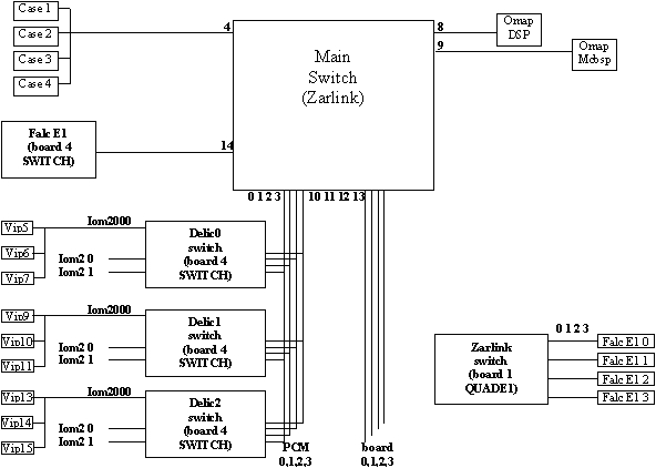
Connection field
- Type – ZARLING
- Total capacity 512 channels
- Maximum number of simultaneous calls up to 172 – according to configuration
 |
| Pozice 2 | 0 on PRI = 1 | 1 on PRI = 2 | 2 on PRI = 0 | 3 on PRI = 3 |
| Pozice 3 | 0 on PRI = 2 | 1 on PRI = 0 | 2 on PRI = 1 | 3 on PRI = 3 |
| Pozice 4 | 0 on PRI = 0 | 1 on PRI = 1 | 2 on PRI = 2 | 3 on PRI = 3 |
Switch: 0, 1, 2, 3
- The card ports are marked blue, the Switch buses are marked red.
- The CPU card and the SWITCH card are filled 1:1.
- If more than 3 ports are occupied on the card or cards in the positions 2, 3 and 4, the PRI cards must be equipped with another ZARLING connection field. This ensures that the call channels of all ports are connected to the basic connection field of the SWITCH card.