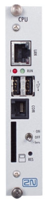
2.4 CPU Card
The card is an inseparable part of the basic module.
- It contains all necessary interfaces needed for the communication with the system.
- It is only installed in the basic module, always in the position with the 0 HW address.
 |
LAN
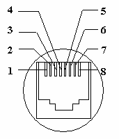 |
- Interface type – Eth T-Base 10/100
- Connection – RJ45
- Pin1= transit +,
- Pin2= transit -,
- Pin3= receive +,
- Pin6= receive -
USB
 |
- Interface type – USB 1.1
- Connection – 2x USB-A
- Physical layer – Low Speed – 1.5Mbits/s
- Power supply – 5V
- Consumption – max. 100mA
COM
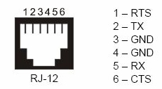 |
- RS 232C interface connection
- Interface type – RS232C
- Configuration – 115200Bd, 8 bit, parity: none, stop bit: 1
- Connection – RJ-11 (6x6)
- Pin1= TxD -,
- Pin2= TxD +,
- Pin3,4 = GND,
- Pin5= RxD +,
- Pin6= RxD -
MMC
- MMC cards slot – MMC 7 pins
- MMC 4.0 and MMC Plus 13 pins
- Buses – 1-bit (MMC) and 4-bit (MMC4.0 and MMC+)
- Power supply – 3,3 V
- Reading speed – up to 22 Mb/s
- Writing speed – up to 18 Mb/s
- Maximum recommended capacity – 4 GB
    |
RES
The Reset button will reboot the entire system.
Maintenance switch
- ON position – appliance switched on
- OFF position – appliance switched off, the position is equipped with a 3 s by-pass for the switching into the Maintenance Mode
- Maint. position – appliance in the maintenance mode, the line cards supply switched off and the card drivers stopped in order to enable their maintenance or exchange, or changes in the port set-up.
After the switching into the ON position, the card drivers are launched and their power supply is switched on – no need for the re-launching of the entire system and starting of all processes.