2.3 Mounting - Universal version
Safety Precaution
Safety
- The telephone line supply cable, microphone, loudspeaker, LED indicators, ALARM button and CANCEL contact, including cabling, and the board with electronics are connected with a telephone line and so remember to ensure during installation that the user cannot touch these product parts and is protected against an electrical accident by a minimum isolation distance of 1.5 mm, or an isolation barrier of a minimum break-down voltage of 1,500 V!
Caution
- The location, appearance and designation of the communicator controls (e.g. the ALARM button) have to comply with the applicable lift standards.
ST Location
ST may be mounted into any position as needed, the optimum elevation being approximately the height of an adult's mouth. The ST mounting place must be beyond the reach of the operating personnel (see the Safety Precautions).
Caution
- You are not recommended to mount the electronics without the mounting panel because the panel works as an electric isolation barrier and the manufacturer cannot guarantee safety if it is not used.
Mounting of Panel with ST Electronics
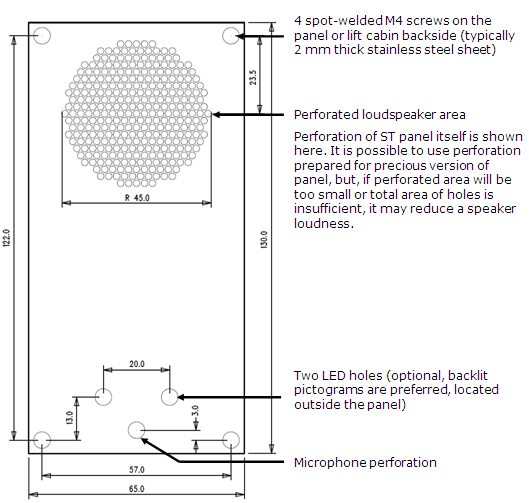
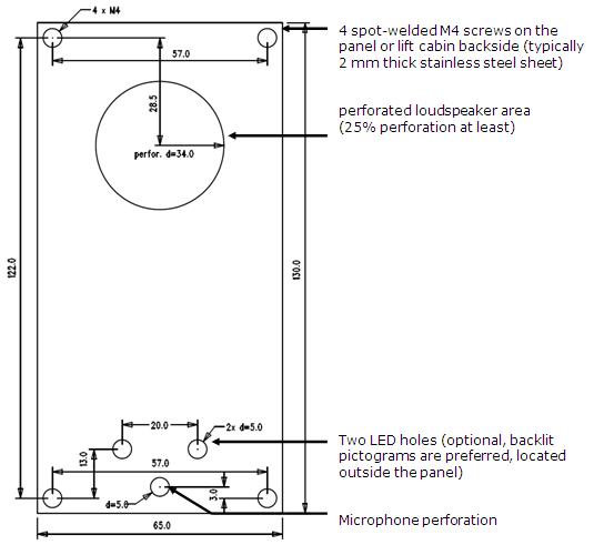
To mount the ST panel onto the lift car interior wall surface you need 4 spot-welded M4 screws in the pitch of 57×122 mm and a sufficiently perforated loudspeaker area (may be larger than as shown on the figure, yet in no case may overlap the panel size to avoid acoustic short-circuit), a microphone hole and 2 LED holes if necessary.
Mounting drawing for version with 50 mm speaker
 |
Mounting drawing for version with 40 mm speaker
 |
Fit the mounting panel in such a way that it cannot vibrate while operation. There may be no gap between the wall surface and the ST panel, or, if any, it must be sealed properly to eliminate acoustic short-circuit of the loudspeaker and acoustic coupling between the loudspeaker and the microphone (see later).
Caution
- Make sure that the microphone hole is sealed properly to sense the lift cabin sounds only and suppress the noise coming from the shaft or cavity behind the wall!
Off-Panel Microphone Mounting
By default, the microphone is placed directly on board (see drawing for microphone position). If required, a cable-equipped microphone is available, fitted to a holder of the size of 25×25 mm with self-adhesive foil. This helps mount the microphone behind any hole in the wall surface (a hole with the minimum diameter of 3 mm, or a group of smaller holes of the same total area). Board of version 5 and higher has both onboard microphone and the connector for external one. Switching to external microphone is automatic (external microphone is detected).
The minimum distance between the loudspeaker and microphone centers is 90 mm. With a smaller distance an acoustic coupling might occur. A bigger distance, however, is allowed.
Warning
- Make sure that the microphone hole is sealed properly against noise coming from the cavity behind the wall in order and thus senses the lift car sounds only!
Off-Panel Loudspeaker Mounting
By default, the loudspeaker is panel-mounted. Since half of 2010, every speaker is connected by cable. It allows installation of amplifier module. You can also slide the loudspeaker out of its panel bed and place separately, if necessary. See safety notice in this case, see bellow!
Caution
- In that case seal the loudspeaker properly to eliminate acoustic short-circuit between the front and back loudspeaker sides (the grid may in no case overreach the loudspeaker area to avoid acoustic short-circuit.
Safety
- Keep the minimum electric isolation between the panel and the loudspeaker of 1500 V
- Keep the minimum isolation distance between the panel and the loudspeaker of 1.5 mm.
- 40 mm speaker is equipped with a rubber sealing. Do'nt remove it!
50 mm speaker must be placed at insulating (non-metallic) surface. Otherwise, ask manufacturer for an external panel, as shown at right (it is n ot included)
Caution
- You are not recommended to install the microphone and loudspeaker on relatively distant places in the lift car (e.g. one on the ceiling and the other on the wall) because the users should easily locate the loudspeaker (its grid or perforation) and expect to find the microphone close to it.
Indicator Mounting
You can choose any of the following three ST status indication options:
- Use the backlit pictograms integrated in the lift cabin control panel.
- Add optional light guides to the existing ST LEDs to conduct light to two panel holes.
- Connect two optional LEDs to ST with a cable.
Safety
- If the LEDs are cable connected, make sure that the electric isolation between the panel and the loudspeaker is 1,500 V at least.
- Make sure that the isolation distance between the panel and the loudspeaker is 1.5 mm at least.
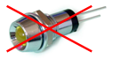
- You are prohibited to use standard metal LED holders (for an example see the figure to the right).
 |
Note
- Make sure that your way of indication complies with the applicable legal regulations. Indicators, however, are unnecessary for ST operation (communication).