2.2 Electric Installation
Electric Installation Step by Step
It is very easy to connect 2N® SIP Mic electrically. Just find the connectors and controls for initial connection on the back panel:
- connect the additional microphone to the upper connector,
- connect the UTP cable,
- connect a 12 V power supply to the back connector (unless PoE is used).
Caution
- Be sure to connect the 2N® SIP Mic power supply as the last step. The same applies to PoE supply from the LAN.
Insert the enclosed microphone into the DIN 3P connector on the 2N® SIP Mic upper side until its clicks into position. Press the locking button and pull out the microphone to disconnect it.
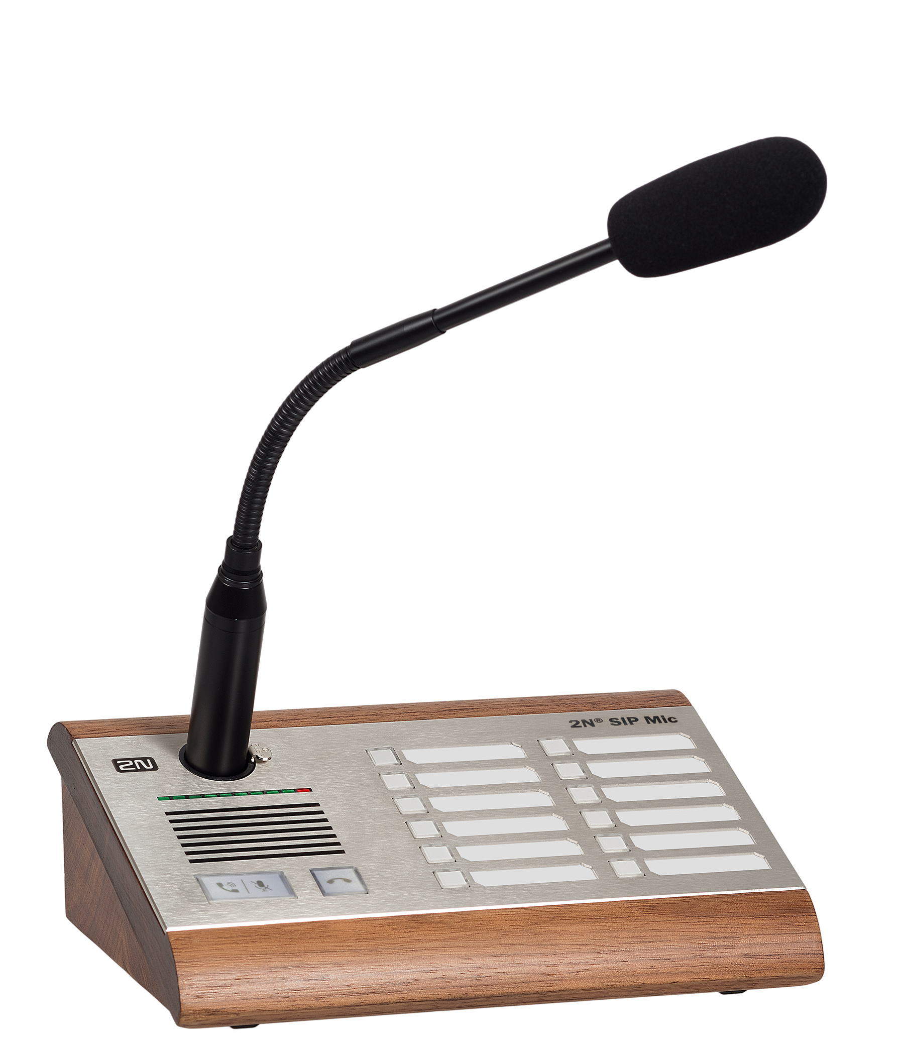 |
Microphone Connection
LAN Connection
2N® SIP Mic can be connected to a standard local area network using a LAN interface via the RJ-45 connector on the back panel. Always use CAT-5d or higher class cables for reliability reasons. The interface supports 10/100 Mbps and can be PoE supplied (IEEE 802.3af).
LAN Connection
The LAN interface is equipped with the Auto MDIX function for automatic straight or cross-over cable detection.
The LAN interface can also be used for the 2N® SIP Mic power supply through active network elements or injectors meeting the IEEE 802.3af standard.
Caution
- We recommend the use of a LAN surge protection.
- We recommend using a shielded SSTP cable.
Power Supply Connection
2N® SIP Mic can be fed using active network elements or PoE injectors via the LAN interface. In case this option is unavailable, for proper operation use a 12 V DC / 2 A (Part No. 914102) power supply. External and PoE supplies can be combined as the device can be fed from both the supplies at the same time. Thus, the other supply can be used for backup, for example.
Connect the device via the power jack on the 2N® SIP Mic back side as shown in the figure below.
2N® SIP Mic consumption with different power supplies:
| Power supply | Consumption |
|---|---|
| PoE, IEEE 802.3af | 8 W |
| Part No. 914102x | 8 W |