4.3 Configuration Program
This application is used for basic configuration of the terminal. This subsection provides details on its environment and basic functions. Launch the application from the directory into which you installed it.
Note
- The 2N® SmartCom Terminal Configuration Program installation requires 20 MB of free disk space at least.
Details on Application
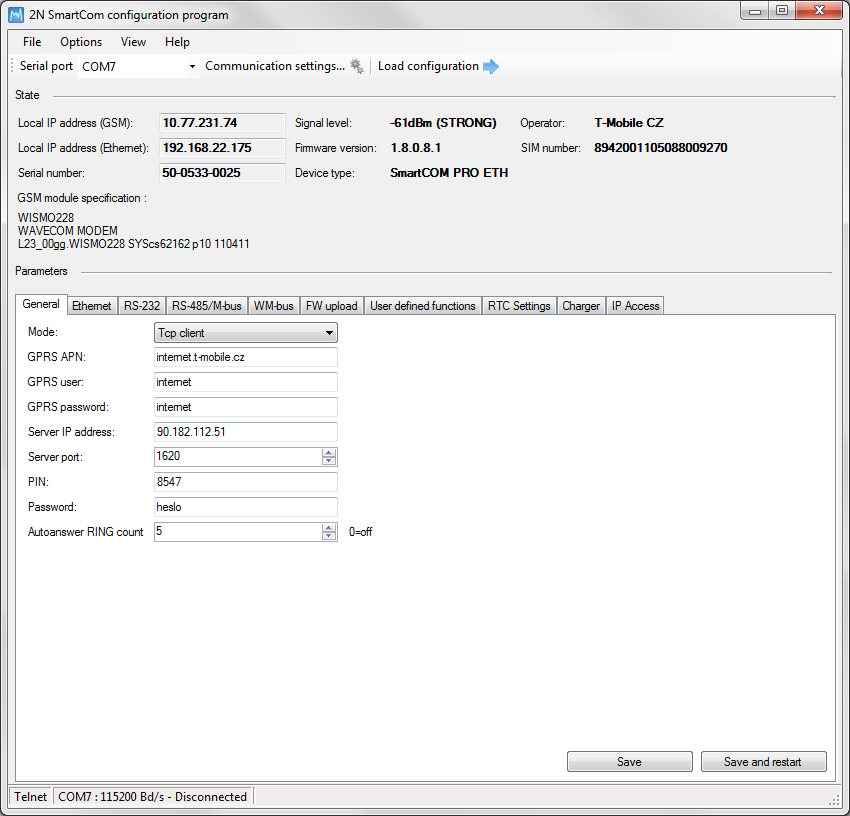 |
Figure: Terminal Config Window
The figure above shows the 2N® SmartCom Terminal Configuration Program (hereinafter referred to as Terminal Config) window. The main toolbar helps you select the Serial port for connection to 2N® SmartCom PRO (hereinafter referred to as terminal). This list includes all available serial ports installed in the PC on which the application is running.
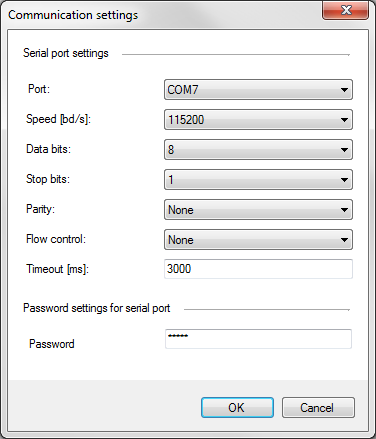 |
Obrázek: Communication Settings
Having selected a port, set the communication parameters to adjust communication rates and signal transmission parameters for the serial port. The 2N® SmartCom PRO factory values are set here by default. Refer to the Communication Settings figure above.
No password is requested by default for the RS 232 port and so nothing has to be filled in. Passwords may be different for different terminals. If a password is requested, enter the password into the dialogue window displayed during the connecting process.
The last main toolbar button helps you load configuration from the terminal connected. The application gets connected and reads out all relevant data.
Tip
- The application connects to the selected terminal, identifies the RS 232 mode (DATA or COMMAND), switches the port as necessary, reads out the data, switches the port into the original mode and terminates communication. This gives the other users continuous access to the terminal.
The State section displays the most important information on the given device.
The IP address, serial number, firmware version, logged-in provider and signal level are displayed. The SIM ICCID (Integrated Circuit Card ID) is displayed, which is not the SIM phone number, i.e. MSISDN, but a unique SIM serial number. There are no two identical ICCIDs at one moment. These 19-digit numbers start with 8942 for the Czech Republic.
Moreover, the section provides information on the GSM module: type, manufacturer and firmware version.
The Parameters section helps you view and set the 2N® SmartCom PROparameters.
There are useful submenus in the application main menu. Use the File menu to read configuration, import/export configuration or reset the connected terminal. Via the Options menu you can adjust communication parameters and/or change the default language (CZ or EN). The View section helps you disable the tabs that are not frequently used and occupy too much space. Open the View menu and specify the tab(s) to be seen.
Tip
- The General tab is always visible. It is the only menu that cannot be disabled.
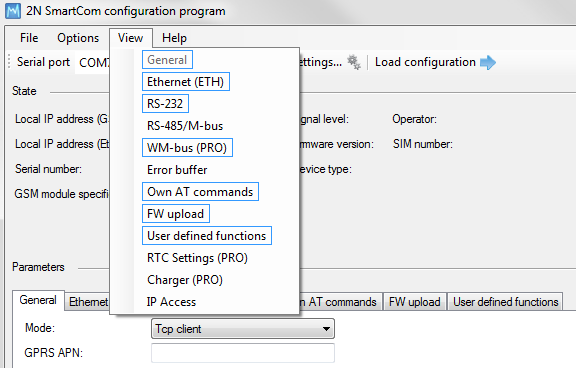 |
View Menu
Go to Help to know details on the Terminal Config manufacturer and version.
Use of Application
Tip
Not all tabs are accessible to all device models.
- General, RS 232, RS 485 / M-Bus, Error buffer, Own AT commands, FW upload, User defined functions and IP access are accessible to all terminals.
- The WM-bus, RTC Settings and Charger tabs are available to the PRO and PRO ETH terminals only.
- Ethernet is accessible to the PRO ETH terminals only.
Having read configuration, go to the General tab of the Parameters section.
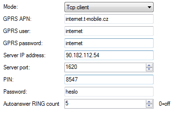 |
Figure: General Menu
Here you can set all parameters comfortably like with the AT commands described in S. 4, i.e. all GSM commands plus automatic answer parameters. Click Save to save the values. Click Save and restart to apply the changes immediately.
The Ethernet menu is only available to terminals equipped with an Ethernet port. Set the primary data flow channel, LED signalling functions, obtaining IP address from the DHCP server or static setting and DNS server use.
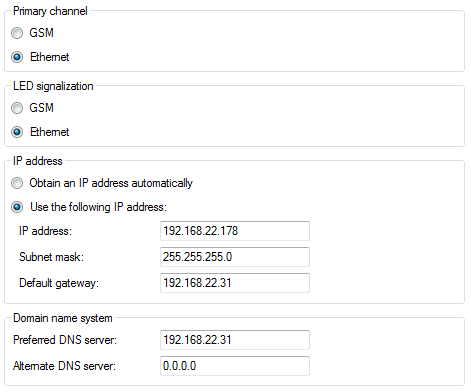 |
Ethernet Menu
Use the RS 232 and RS 485/M-Bus tabs to set communication parameters for each port. Set the password request enable and AT mode upon power up for RS 232. You can set the WM-Bus interface here: set the operating and decryption modes for the module (in/outside the module).
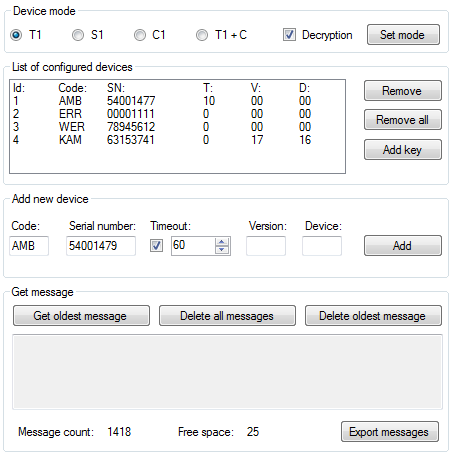 |
WM-Bus Menu
Click on a device in the List of configured devices to select the device and push the buttons to the right to remove the device or add the decryption key to it.
Caution
- The keys are added to the WM-Bus module directly for security reasons and are not displayed in the configuration. Therefore, be careful while configuring the keys.
- A key adding error may lead to a decryption error.
Furthermore, you can Add a device to the list. Enter the device code and serial number. Complete the timeout, e.g., in case the selected device sends multiple identical pieces of information in a short time interval. The remaining parameters are optional and need not be specified.
Warning
- Contact the device manufacturer for precise identification details.
- Enter all the identification parameters of the new device to enable encryption in the device.
Display received messages in the Get message section. The messages are read from the database starting with the oldest one. The Message count displays the count of received messages in the terminal and the amount of free space. When there is no free space, the oldest record will be deleted to make space for a new message. Push the Export messages button to export all the messages stored in the terminal into a PC file in order to make space for new messages.
The Error buffer helps you display the error codes captured during the operation. If no error has occurred since the last clearing date, ^SCERR: NO ERROR will be displayed. If an error occurs, the error code will be displayed. Click on the Error code table button to display the message decryption window.
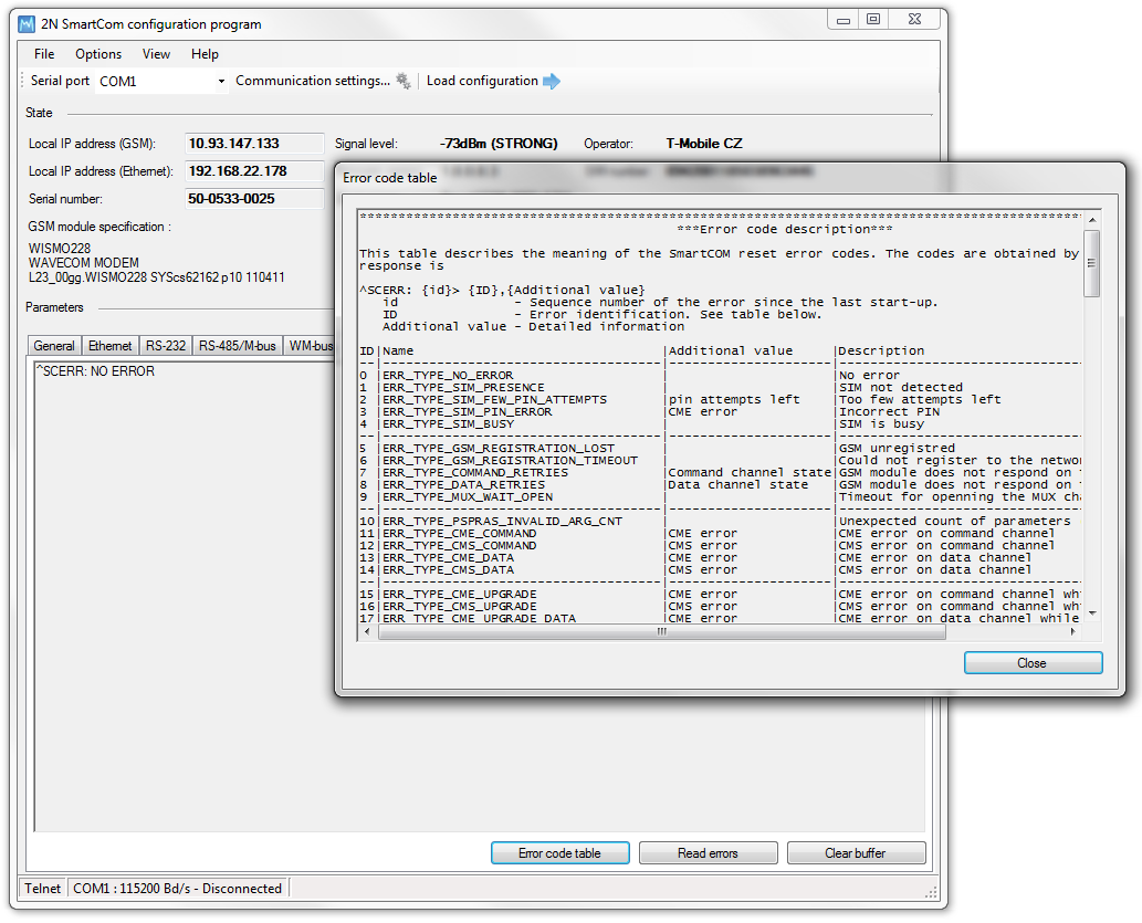 |
Figure: Error Buffer
Use the Own AT commands tab to enter commands of your own for parameter setting. The tab behaves like a terminal. Enter a string into the AT command field corresponding to the supported commands listed in Subs. 4.2. Click Send to send the command to the connected 2N® SmartCom PRO terminal and get the response in the field below the command. A list of 20 last-applied commands is displayed to the right.
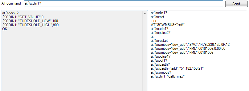 |
Figure: User Defined AT Commands
The last tab helps you upgrade firmware via the terminal COM port. Select the path to the current firmware file and press Start to initiate the upgrading process, which is signalled by the progress bar below. When the process is completed, the terminal will get restarted.
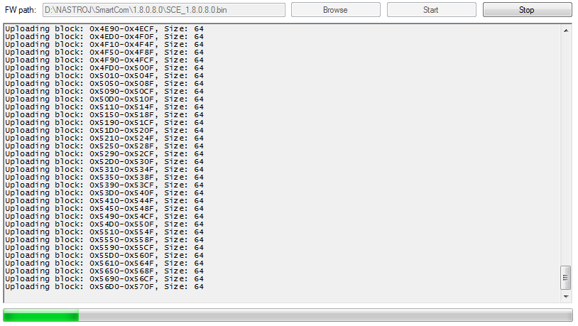 |
Figure: FW Upgrade
Caution
- Make sure that the terminal FW supports FW upgrade via the COM port to make the process successful. The minimum terminal FW version is 1.4.0.
The User defined functions tab helps you set the UDF graphically and more easily in the application than using an AT command in the terminal. Just select the required functions and set their parameters and the application itself will generate the relevant AT command to be sent to the terminal or to be stored for later use. Refer to Console for the current terminal communication listing and to Current settings for the list of configured commands in the terminal.
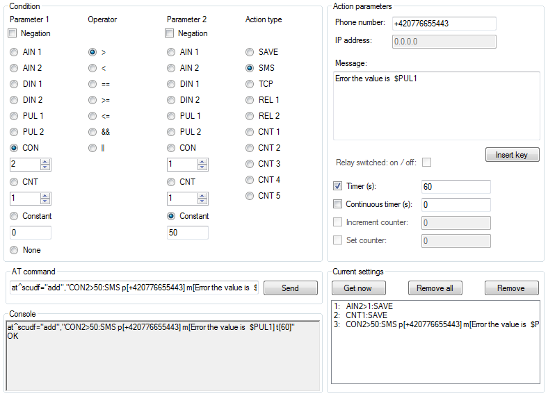 |
User Defined Functions Menu
Refer to Subs. 3.5 for more details on the UDF setting options.
The RTC settings tab displays the current date, time and time zone data. You can also synchronise the device time with your PC time or set the device time manually. Click Save to confirm the settings.
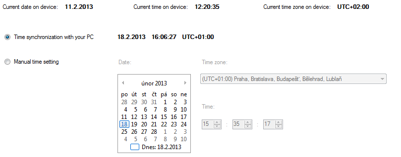 |
RTC Settings Menu
Charger is another setting option. It displays the back-up battery charging state for the PRO terminals. You can enable/disable the function and set the maximum charging voltage and current.
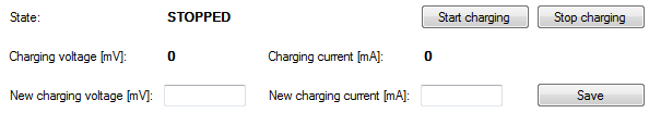 |
Charger Menu
IP access is the last accessible tab. You can define the IP addresses from which it will be possible to access the terminal. Attempts from non-listed IP addresses will be ignored. Press ON to enable the function and Add to add an IPv4 address to the list. Click on an item for selection and push Remove to delete an address from the list.
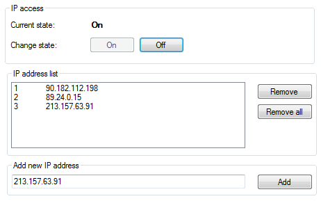 |
IP Access Menu