2.1 Description
2N® SmartCom PRO consists of a PCB carrying a power supply and RS 232, RS 485/M–Bus/MDB interfaces. Connectors for optional devices are located in the upper part of 2N® SmartCom PRO. There are two output controlling bistable relays and three inputs with a common ground for current/voltage measuring or S0 input pulse counting. PullUp from the supply voltage or an internal 3V3 supply can be used for the S0 input. The board also includes four extender slots. An optional WWAN module for continuous Internet connection via GPRS/UMTS/LTE can be mounted into one of them. The optional Wireless M-Bus and ZigBee modules can be mounted in 2 slots on the device top. The fourth slot will help connect a back-up gel–lead–acid accumulator charger in the future. The board also includes a real time clock backup. An optional Ethernet connector is mounted on the bottom too. Refer to the figures below for details. The whole 2N® SmartCom PRO system is enclosed in a solid aluminium case. Mount the case on a DIN rail for easier installation.
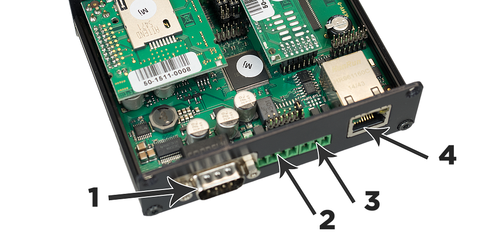 |
Description of 2N® SmartCom PRO (Bottom View)
- RS 232 connector
- 9-pin D-sub
- Power supply and battery terminal board
- +Uin, -Uin – supply voltage terminals
- +Batt, -Batt – gel–lead–acid accumulator terminals
- RS 485/M-Bus/RS232 connector (bus type according to the selected version)
- +,-,GND for RS 485
- A, B, GND for M-Bus
- Tx, Rx, GND for MDB
- Ethernet interface (optional)
- RJ-45
- RJ-45
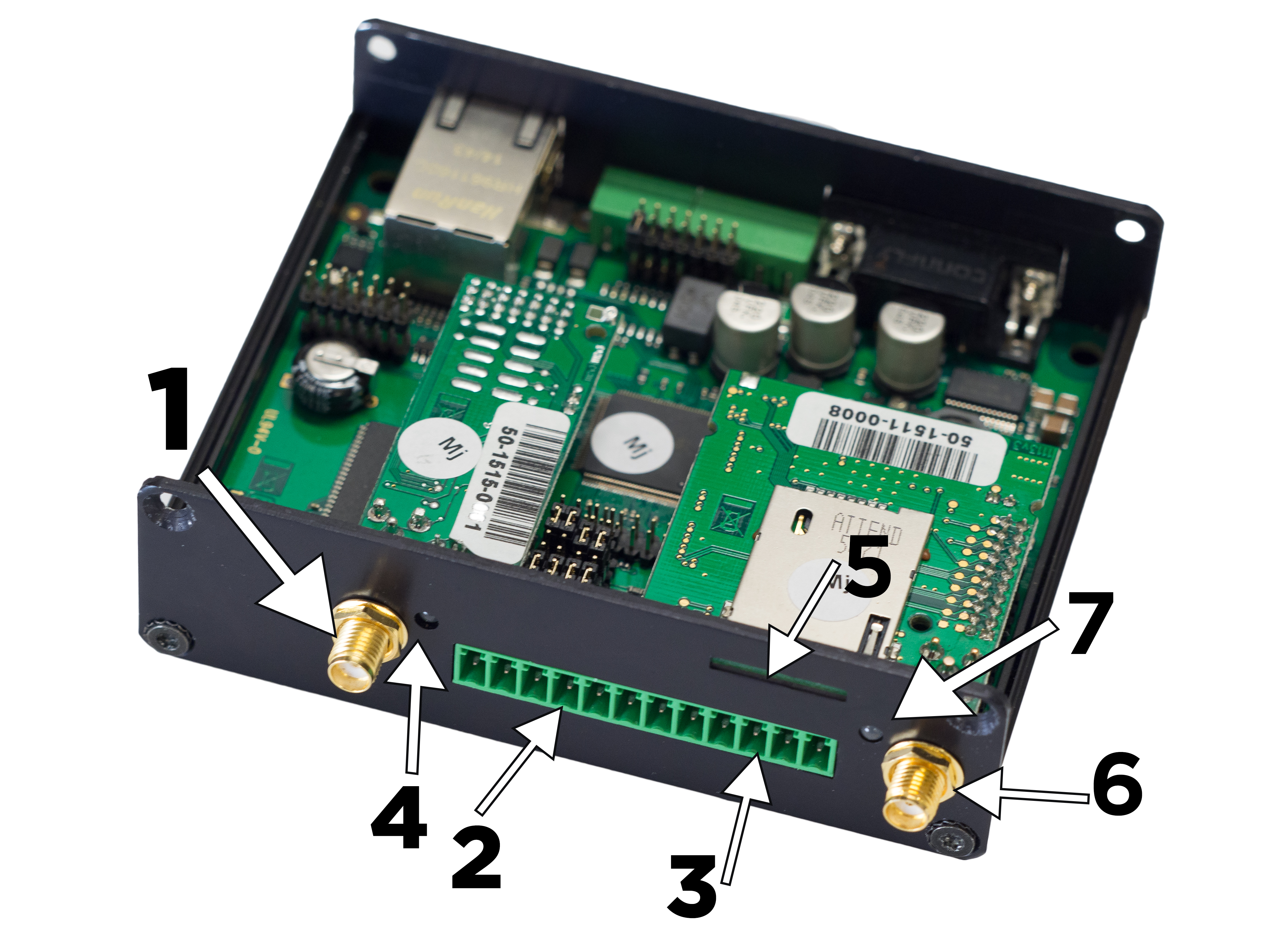 |
Description 2N® SmartCom PRO (Top View)
1. ZigBee or Wireless M-Bus antenna SMA/RP-SMA connector (optional)
2. Input/output circuit terminal board (from left):
- IN3, GND, IN2, GND, IN1, GND – input circuits (input type according to the jumper settings, refer to Subs. 3.3)
- GND – common ground for sharing with input circuits!
3. Relay terminal board (from left):
- RE2 – switching relay contacts
RE1 – switching relay contacts
4. Signalling LEDs
- From right: MOD1, MOD2 (optional). Available only if the module is mounted.
5. SIM holder
6. WWAN antenna SMA connector
7. Signalling LED
- According to the WWAN or ETH settings