3.6 Telephony Services
Before the description of all items of the Telephony services menu, a short introduction about the VoIP Network Arrangement and Routing behaviours is given there.
VoIP Network Arrangement
VoIP telephony communication has two components – signalling and voice. Signalling is primarily used for establishing and terminating calls, telephone login to a PBX, negotiating parameters and control of the speech/voice channel. The voice channel is only used for transmission of encoded digitised voice information.
Typically, VoIP telephones are operated together with a PBX, which coordinates their traffic. For a schematic arrangement see fig.39. The VoIP telephony PBX is a software application that looks like a traditional PBX. Its functions include mainly numbering plan consistence maintenance, routing, user or telephone rights, call billing, call forwarding, DISA, etc. But it can integrate more functions, e.g. voicemail. SIP telephone PBXs are usually called SIP proxies while PBXs for H.323 are called gatekeepers.
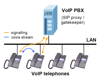 |
Figure 3.30: VoIP PBX Arrangement
To work properly, a VoIP PBX must process all signalling traffic. Unlike this, voice channel data are transmitted directly between the terminal points. This is, among others, a difference from the model described below. It is because a PBX is not necessarily required in the IP telephony. Signalling protocols are designed in such a manner that it is possible to call from one terminal to another directly, without any mediator. To do this, you have to know the full ID of the terminal to be called, i.e. also the IP address and destination port, of course. This is the main disadvantage compared with the preceding model for multiple-telephone locations.
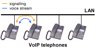 |
Figure 3.31: "Point-to-Point" Arrangement
If you use a PBX, the terminal points must know the PBX address only. The PBX is able to route requests according to information acquired in the process of telephone login to the PBX. With the "Point-to-Point" arrangement, all telephones must be equipped with information on surrounding telephones. This model is mostly applied in direct calling via the Internet where you do not want or cannot use services of any telecom provider. The 2N® OfficeRoute gateway is capable of working in both the types of environment, with a PBX and without a PBX.
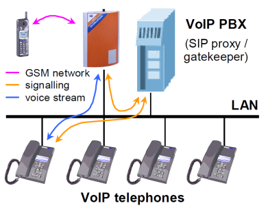 |
Figure 3.32: VoIP-to-GSM Gateway with PBX
It can even replace the PBX completely for SIP telephones because it is equipped with an integrated SIP proxy. This simplifies the VoIP network structure as shown in Fig. 3.33.
 |
Figure 3.33: 2N® OfficeRoute as SIP Proxy
Although call interconnection between VoIP and GSM networks is the primary function of 2N® OfficeRoute, the gateway can also be used for bridging VoIP networks with different signalling standards – SIP and H.323. For such arrangement see Fig. 3.34.
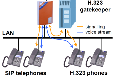 |
Figure 3.34: 2N® OfficeRoute as SIP Proxy - H.323 Gateway
The situation shown in fig. 43 differs from simple SIP-based call connection in that the gateway transmits both signalling and voice channels here, like in interconnecting calls from VoIP to GSM. This results in a certain limitation of the maximum number of calls due to a limited hardware pass-through capacity of the gateway.
Routing
Routing means a process of retrieving a route from the calling party to the called one. There are various routing methods according to the type of call and place from which the call is coming.
Within VoIP Network
Speaking of routing within a single VoIP network, we think of the activity executed by the PBX whenever a registered user initiates a new call. The result of this process is a route to another registered user based on the called number analysis. The called number can be an IP telephone, GSM gateway, PSTN gateway, another VoIP PBX, etc.
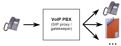 |
Figure 3.35: Call Routing by VoIP PBX
The routing options are dependent on the capabilities of the particular PBX. For SIP-based telephones, a SIP proxy server built in 2N® OfficeRoute can be used as a PBX.
From VoIP to GSM
On coming to an 2N® OfficeRoute VoIP line, a call proceeds to the Least Cost Router (LCR). The LCR decides which line the call shall use for going out. The decision depends on the called number and LCR settings.
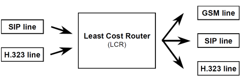 |
Figure 3.36: Routing of Incoming Calls from VoIP
Although the Least Cost Router is, as its name suggests, designed primarily for searching the most cost-efficient route to a GSM network, it is not limited just to this function. Generally, it can interconnect incoming calls from VoIP lines to any lines that are available in the gateway regardless of their types. This is very useful for interconnecting heterogeneous VoIP networks, such as SIP and H.323 environments.
Incoming Calls from GSM
A special routing mechanism is applied to calls coming to the 2N® OfficeRoute gateway from GSM networks.
 |
Figure 3.37: Routing of Incoming Calls from GSM
As selected, the GSM router:
- forwards the call to a fixed operator;
- plays ME message and allow to dial local or remote number according to the ME CLIP; or
- forwards the call to the DISA automat where the calling party chooses the route using a voice menu and tone dialling.
Since incoming calls from GSM networks can only be routed to VoIP lines in the gateway it is impossible to connect a call back to the GSM network in this type of routing. This, however, does not mean that this operation cannot be executed on another routing level, e.g. in a PBX.
If the VoIP telephones used are equipped with the Calling Line Identification Presentation (CLIP) function, either the internal number of the gateway output line used for the incoming GSM call, or the CLIP obtained from the GSM network can be displayed. This VoIP line parameter is set at the first option by default. To make the gateway convey a public number to the VoIP telephone it is necessary to ensure that all routing elements be able to process the CLIP correctly in the opposite direction.
Devices
Call interconnecting and routing in 2N® OfficeRoute takes place between lines. This means that where no line is available the gateway cannot set up a call. Nevertheless, the notion 'line' is less materialistic in VoIP gateways than in classical telephone systems.
To make some equipment work as a gateway, another line at least has to be created to the VoIP environment. This line is either used for the gateway - VoIP PBX connection or a direct gateway - VoIP telephone connection. From the viewpoint of the network environment of the gateway, a VoIP line represents a virtual VoIP telephone set.
It is possible to define more VoIP lines than one in the gateway. Then the gateway appears like a system of multiple virtual VoIP telephones. All line types are equal for the routing and connecting purposes.
SIP Lines
One or more lines can be defined in 2N® OfficeRoute for communication with some other SIP using VoIP equipment. Each line has a unique number and receiving UDP port. You can register the line at the SIP proxy or communicate directly with another VoIP terminal. The registration can be either anonymous or related to the gateway authentication.
By default an internal SIP line is prepared. This line is necessary for you to make calls out of the SIP proxy.
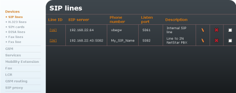 |
Figure 3.38: List of SIP Lines
Modify SIP Line
To make calls out of the SIP proxy you have to modify the internal SIP line ID [16]. To make a trunk to a VoIP provider create a new SIP line.
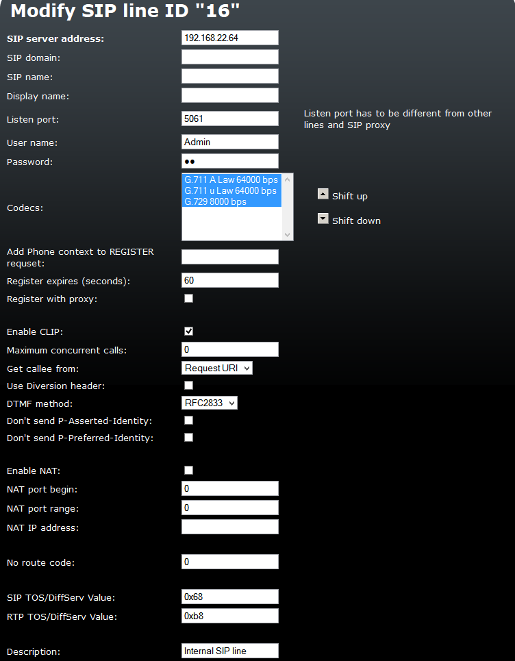 |
Figure 3.39: Modify Internal SIP Line
- SIP server address – Change the default IP to the 2N® OfficeRoute IP address for internal SIP line. While creating a new line, enter the IP address of your VoIP provider. If a port other than 5060 is to be used (for provider or proxy), it should be specified behind a colon (192.168.22.63:5071).
- SIP domain – It is not necessary for the internal SIP line.
- SIP name – The internal SIP line SIP name is '1111'. For a new line enter the SIP name according to your VoIP provider.
- Display name – The line name to be displayed. An optional parameter.
- Listen port – Each line has to use a different listening port.
- User name – User name is unnecessary for the internal SIP line and may be deleted. For a new line enter the user name according to your VoIP provider.
- Password – Password is unnecessary for the internal SIP line and may be deleted. For a new line enter the password according to your VoIP provider.
- Codecs – This parameter is necessary to highlight the codecs to be used (press and hold CTRL to select multiple codecs). You can shift the codecs to define their priority.
- Add Phone context to REGISTER request – This can be useful in some special cases. Mostly it is unnecessary to fill in this item.
- Register expires – Enter the value according to your VoIP provider. Unnecessary for the internal SIP line.
- Register with proxy – Unselect this checkbox for the internal SIP line. For a new line check it according to your VoIP provider.
- Enable CLIP – Select this checkbox for the internal SIP line.
- Maximum concurrent calls – Limit the count of concurrent calls via the selected SIP line..
- Get callee from – This can be useful in some special cases. Mostly it is unnecessary to change these settings.
- Use Diversion header – Tick off to include the Diversion parameter in the SIP INVITE message, carrying information on the originally called line of call forwarding occurred during the call.
- DTMF method – Choose method for transmiting DTMF characters for the SIP line.
- Don't send P-Asserted-Identity – Tick off to deactivate the P-Asserted-Identity header in the INVITE message. This header is used for CLI information transmission even if CLIR (Calling Line Identification Restriction) is enabled.
- Don't send P-Preferred-Identity – Tick off to deactivate the P-Preferred-Identity header in the INVITE message. This header is used for transmission identification of user which has call forwarding enabled.
- Enable NAT – Check off this item in case the VoIP module is behind the NAT or firewall.
- NAT port begin – Set which port will be used first for the RTP protocol.
- NAT port range – Set how many ports will be used for RTP packets.
- NAT IP address – The public IP behind the PBX VoIP module.
- No route code – Enter the SIP cause code for terminating call if the route is not defined.
- SIP TOS/DiffServ Value – Set one of the SIP packet parameters, which sets priority in packet processing by network elements.
- RTP TOS/DiffServ Value – Set one of the RTP packet parameters, which sets priority in packet processing by network elements.
H.323 Lines
Another signalling standard supported by the IP telephony is a group of protocols called H.323. It could be set only one H.323 line, but it can transfer more calls at the same time. This line can log in to the Gatekeeper or communicate directly with VoIP telephones or other gateways.
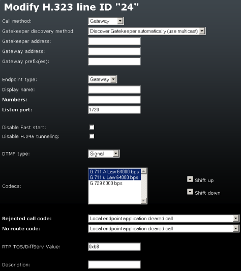 |
Figure 3.40: H.323 Line Details
The form contains the following fields:
- Call method – Define how to initiate a new call. There are three options
- Direct – calling including identification of the fully qualified network name of the called line;
- Gatekeeper – the selected Gatekeeper shall find the route and set up a call;
- Gateway – calling via a selected gateway.
- Gatekeeper discovery method – defines how to find the available Gatekeeper address. The address can be entered statically or determined by network retrieval.
- Gatekeeper address – if not determined by network retrieval, the Gatekeeper address must be entered in this field.
- Gateway address – the address of the gateway to be used for calling if the Gateway calling method is selected.
- Gateway prefix(es – the prefixes used by the gateway for registration.
- Endpoint type – the gateway can register itself to the Gatekeeper either as a gateway for a prefix (destinations starting with the prefix are routed through the gateway) or as a terminal (virtual telephone).
- Display name – the text to be displayed to the called line.
- Numbers – numbers of the line working in the terminal mode.
- Listen port – the TCP port on which the line receives H.323 connections.
- Disable Fast start – the Fast start method provides a faster start of the voice stream while a new H.323 connection is being set up.
- Disable H.245 tunnelling – disallows the use of H.245 tunnelling.
- Disable Early media start – disallows the use of the Early media start method. This method establishes the voice channel before the call has been set up completely. It is useful for transmission of the so-called 'progress tones' from the GSM network.
- DTMF type – choose the set of supported DTMF tones; either numbers only (the Signal option) or all alphanumeric characters (the Alphanum option).
- Codecs – a list of codecs to be provided by the gateway for voice channel negotiations.
- Rejected call code – the code that the gateway returns back to the Gatekeeper/gateway in the case of rejected call.
- No route code – the code that the gateway returns back to the Gatekeeper/gateway in case no route (no GSM module/SIP line/H.323 line/SIP phone) is ready for a call. This is used mainly for overflow/emergency routing.
- RTP TOS/DiffServ Value – Set one of the RTP packet parameters, which sets priority in packet processing by network elements.
- Description – any text that describes the meaning of the form.
SIM Cards
If you operate the gateway with different provider's SIM cards, you will definitely want to use a GSM provider's SIM card for GSM call routing. When a new SIM card is inserted, the gateway creates automatically a 'SIM card – xxx' line where xxx is the SIM card ID (typically printed on the card next to contacts). The physical location of the SIM card does not matter in call connection.
Note
- You are strongly recommended to power off the unit before inserting/removing the SIM card.
Each SIM card inserted in the gateway has a set of parameters of its own. Their values are bound to the card ID and remain stored in the gateway even after the SIM card is removed. Thus, if the SIM card is reinserted, the parameters need not be reset. The list of cards with available configuration parameters is displayed in a table on the introductory page of the SIM card configuration.
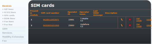 |
Figure 3.41: List of Available SIM Cards
In this menu (Fig. 3.41) you can see the list of inserted SIM cards and also get the credit on each SIM card. For this function it is necessary to define the USSD code for getting information on the SIM card credit. The code syntax depends on the provider.
The columns in Fig. 3.41 include:
- Present in module – Mark that the SIM card has been inserted in the gateway.
- SIM card number – Unique card identifier. It is usually printed on the card next to contacts. By clicking on the number you display the card setting detail.
- Provider ID – Mobile network provider's identifier.
- Provider name – Mobile network provider's name.
- Last USSD message – Shows the last obtained USSD message.
- Description – Text entered by the administrator.
By clicking on the pencil symbol you get into the line setting detail and can change the settings. The cross is used for deleting a line.
Modification of SIM Card Parameters
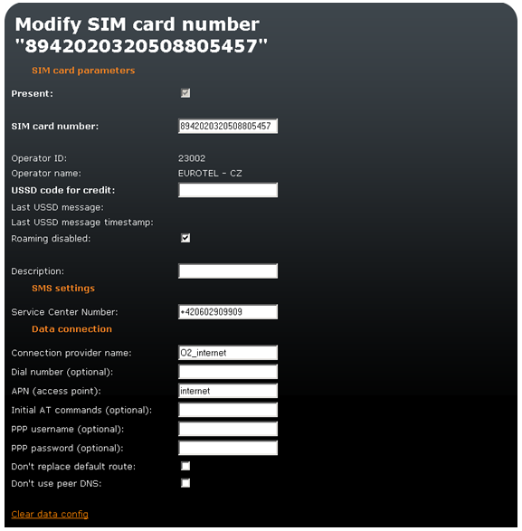 |
Figure 3.42: Modify SIM Card Form
- Present – Indicates whether the SIM is present in the tray at the moment.
- SIM card number – Information on the SIM serial number (IMSI).
- Provider ID – Provider's network code.
- Provider name – Provider´s name.
- USSD code for credit – Here you can also enter the USSD code for credit check for prepaid SIM cards. If you fill in the proper USSD code and the SIM card is prepaid, you can obtain credit information by clicking on 'Get credit' in the SIM card list.
- Last USSD message – Shows the last obtained USSD message.
- Last USSD message timestamp – Shows the last USSD message timestamp.
- Roaming disabled – Disable/enable roaming for the given SIM card. Roaming is disabled for new SIM cards by default and has to be enabled if necessary.
- Description – User description of the SIM card.
- Service Centre Number – Enter the Service centre number. It is necessary for SMS sending.
In order to use the SIM for data/Internet connection (for GPRS/EDGE/UMTS/HSPA - 2N® OfficeRoute), you have to set the Connection provider name and APN parameters. The other parameters depend on the network provider – for information refer to your network provider's websites or call the provider's helpline.
- Connection provider name – It can be any name. This field is compulsory.
- Dial number (optional) – Number to be dialled for data connection.
- APN (access point) – This field is compulsory. Complete it in accordance with your provider´s APN name.
- Initial AT commands (optional) – An optional field. You can define here a special AT command for Internet connection.
- PPP username (optional) – An optional field. Enter your PPP user name if recommended.
- PPP password (optional) – An optional field. Enter your PPP password if recommended.
- Don't replace default route – Tick off to leave the default gateway set to LAN (Eth interface) after data connection is established. Change the setting with the data connection off.
- Don't use peer DNS – Define whether the DNS IP addresses should be overwritten in compliance with the data connection provider after data connection is established.
DISA Line
The DISA line can be a standard welcome note or a customised welcome note, VoiceMail system and basic IVR. The DISA line is used for incoming calls, mostly from a GSM network. It might also serve for incoming calls from the VoIP provider.
The DISA line plays a message/dial tone and then waits for DTMF dialling. After receiving a hash (#), it dials the collected digits via a predefined SIP line.
The initial screen of the DISA line configuration shows a table of defined lines.
Click on the pencil icon  to move to the line setting detail for changes. The
  symbol serves for line clearing.
Below the table there is an Add DISA service line  icon. Click on it to display the line defining form. There are also Upload custom DISA messages
  , Upload DISA/IVR package to internal Flash
  and Upload VoiceMail language pack
  icons.
DISA Line Parameters
To add a new line, use the Add icon below the form. To modify an existing line, click on the Modify  icon. Upon the click, the entered data are confirmed and the execution of the relevant operation is requested.
Below the form there are Reset  and Back
  icons. The first one restores the values of all fields as before the form opening and the other moves you to the previous screen.
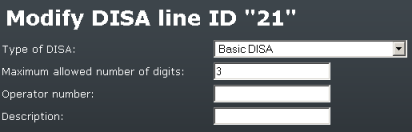 |
Figure 3.43: DISA Line
The form in Fig. 3.43 contains the following fields:
Type of DISA – there are five options
- Basic DISA – Factory-set DISA message.
- Basic DISA with uploaded message – Basic DISA message.
- DISA/IVR on MMC card – DISA message saved in an external memory.
- DISA/IVR on internal flash – DISA message saved on the internal flash memory.
- VoiceMail system – VoiceMail voice menu.
DISA parameters – Parameters are displayed for the selected DISA line. The following options are available
- Maximum allowed number of digits – Maximum number of digits in DISA.
- Operator number – Enter the number to be called if no dialling is made.
- Maximum message length – Define the maximum length of the message to be left to the user in case the call is forwarded to VoiceMail.
- Description – Any text that describes the meaning of a line.
Note
- For examples of DISA settings refer to faq.2n.cz
Fax Lines
To add a new fax line use the Add icon below the form. To modify an existing line click on the Modify icon. Upon the click, the entered data are confirmed and the execution of the relevant operation is requested.
 |
| Figure 3.44: FAX Line |
The form in Fig. 3.44 contains the following fields:
- Fax device – Choose a GSM module with an inserted SIM with the FAX service and fill in the SIM fax number.
- Fax number – Fax line number.
- Description – Any text describing the meaning of an item.
Note
- For examples of FAX settings refer to faq.2n.cz
Note
- The Fax line is implemented only with 2N® OfficeRoute
FXS Line
Note
- The Fxs line is implemented only with 2N® OfficeRoute
This line is set by the wizard. To change some parameters, click on the Modify  icon.
icon.
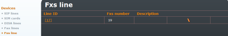 |
Figure 3.45: FXS Line
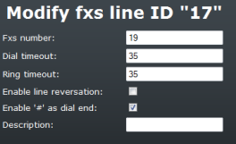 |
Figure 3.46: FXS Line - Modify
The form in Fig. 3.46 contains the following fields:
- FXS number – FXS line number.
- Dial timeout – First digit dialling timeout.
- Ring time – FXS line ringing time for incoming calls.
- Enable line reversal – Polarity reversal at the call beginning and end.
- Enable '#' as dial end – You can use a hash as the end of dialling character.
- Description – Any text that describes the meaning of an item.
GSM
PINs
In this menu you can define the PIN code for each SIM card.
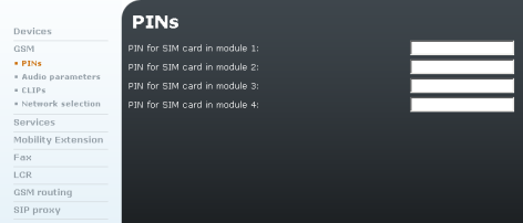 |
Figure 3.47: GSM - PIN
Audio Parameters
You can define the microphone gain and the speaker gain for each module. The range is from -24dB to +12dB for UMTS module and from -24dB to +42 dB (0dB) for GSM modules with a 1dB step.
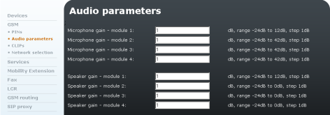 |
Figure 3.48: GSM - Audio Parameters
CLIPs
You can define the CLI function (CLIP - Calling Line Identification Presentation, or CLIR - Calling Line Identification Restriction) and also set the Auto CLIP routing in this menu.
Auto CLIP Routing
The AutoClip routing is used for automatic routing of incoming calls to internal extensions. Records are added to the gateway memory while outgoing calls are made and stored for a defined time. When an internal extension makes an outgoing call and the Auto CLIP routing is enabled, the new records on the calling and called numbers are saved into the internal memory. If the called number calls back in a defined time, the call is automatically routed to the internal extension that was the first to call this number.
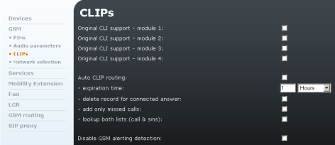 |
Figure 3.49: GSM - CLIPs
The form in Fig. 3.49 contains the following fields:
- Original CLI support – Check off this option to enable the CLI support.
- Auto CLIP routing – Check off this option to enable the Auto CLIP routing function.
- Expiration time – Enter the number of hours for which the records shall be saved.
- Delete record for connected answer – Check off this option to delete a record in the CLIP routing memory after a successful call.
- Add only missed calls – Check off this option to add missed calls only to the memory.
- Look up both lists (call & sms) – Enable the Auto CallBack function after a call or after SMS sending.
- Disable GSM alerting detection – if ticked off, the gateway does not detect alerting and sends the session progress tone immediately.
Network Selection
Use this menu to select one of five network selection rules for the UMTS module.
Automatic is selected by default. Use the icon in the right-hand bottom corner to change the settings. Click on to save the changes, on to reset the changes, or on to return.
Caution
- Make sure that your mobile provider supports login using your selected technology before selecting a network for the UMTS module manually.
- The device will be restarted upon configuration saving.
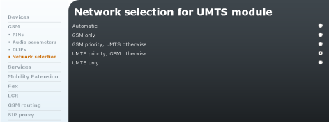 |
Figure 3.50: GSM - Network Selection
Services
Services that enable/disable ME by sending SMS. The SMS has to be sent from the ME user number filled in in the user settings.
To enable the ME function, just send the following SMS to gateway: *<Service code>
To disable the ME function, send: #<Service code>
The gateway responds with a confirmation SMS.
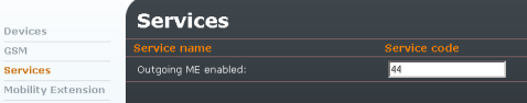 |
Figure 3.51: Services
Mobility Extension
The Mobility Extension (ME) service is a 2N® OfficeRoute feature that makes internal extensions available on mobile phones. Remember to define the Mobility Extension number in the user settings. For the global settings of this function see Fig. 3.52.
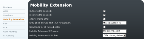 |
Figure 3.52: Mobility Extension
The form in Fig. 3.51 contains the following fields:
- Outgoing ME enabled – Check off this option to enable the Mobility Extension function for outgoing calls.
- Incoming ME enabled – Check off this option to enable the Mobility Extension function for incoming calls (calls from the Mobility Extension numbers defined in the user settings).
- Allow sending SMS – Tick off to enable SMS sending to the ME station at no answer.
- SMS at no answer text – Type the text for SMS at no answer. The %n string inserts the CLIP into the SMS to be sent.
- Send SMS for all missed calls – Tick off to enable sending of SMS at no answer in the case of each call from SIP extension to GSM/UMTS (not matter if the called number is ME or not).
- Mobility Extension SIP route – Define which route shall be used for the outgoing ME calls.
- Mobility Extension DISA line – DISA message for outgoing calls.
Note
- For examples of Mobility Extension settings refer to faq.2n.cz
Fax
2N® OfficeRoute also provides the FAX function, supporting T.38. To change some T.38 fax relay parameters, click on the Modify icon.
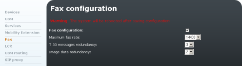 |
Figure 3.53: T.38 FAX Relay Settings
The form in Fig. 3.53 contains the following fields:
- Maximum fax rate – FAX bit rate for T.38 [bit/s].
- T.30 message redundancy – Signalling redundancy.
- Image data redundancy – Image redundancy.
LCR
The Least Cost Router (LCR) is 'the brain' of 2N® OfficeRoute. All call routing rules (inbound and outbound) can be set there.
The purpose of the Least Cost Router is to find the optimum output line for the called number. The LCR process has several stages
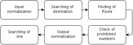 |
Destination searching – Destination means the target party to the call. The destination includes a group and type of line searching in the group. The group is searched according to the prefix of the normalised called number.
Group searching – Group means a logical set of lines. The group definition includes a route time limit within a week.
Line searching – Route can consist of one or more lines. The final line is determined according to the selected line selection algorithm. Three ways of searching are available
- First free line – finds the first free line;
- Cycle – selects the free line with the earliest time of the last call; and
- Free minutes – uses the free line with the highest number of remaining free minutes. Correct tariff rates must be selected for the lines for the method to work effectively.
Caution
- Remember to set tariffs including selected time intervals for the lines to make the second and third searching methods work properly.
Output normalisation the calling and called line numbers are transformed into a normalised format before the call is forwarded to the output line.
Check for barred numbers – The Barred numbers table is searched for match after output normalising and before forwarding to the successfully found output line, and, if a match is found, the call is rejected.
By default, the LCR connects all VoIP calls to the VoIP module without modifying the called number.
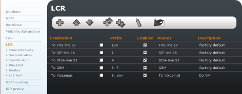 |
| Figure 3.54: List of LCR Rules |
Routing Rules
The routing rules are the core of the LCR system. They consist of a relatively high number of parameters, which make the routing process highly flexible. A guide is available to make your configuration steps as convenient as possible.
Click on LCR in the Telephony services menu to display the pre-defined rules created by the configuration wizard. Click on the icon to add a rule, on  or
or  icon to move a selected rule up or down respectively, on to modify and on
  to delete a rule. You can insert a new rule before an existing rule with
  or after an existing rule with
  . You can set multiple conditions within one prefix using these two options if, for example, you require different routes for different time intervals for one prefix.
All the above-mentioned buttons except for Add are inactive in the initial status (greyish). They will not become active until one routing rule at least is selected by putting the checkmark in the second column of the respective line. By pushing the button activated in this way you get executed the operation above the routing rules selected.
Add Rule
To open the routing rule adding form click on Add or Insert after or Insert before. A new window will be displayed.
The first step is to define the destination. Basically, the destination is a set of prefixes. Looking for the appropriate routing rule, the LCR searches the allowed routing rules from top to bottom for a match between the normalised called number prefix and the destination number prefix. The first matching prefix stops the searching process and the call is routed according to the respective destination rule.
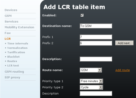 |
Figure 3.55: LCR - Add Rule
The form contains the following fields:
- Enabled – A routing rule can be defined yet not necessarily used in the routing process. Enabled rules are used only.
- Destination name – The destination must be named briefly and clearly, e.g. according to the mobile network provider or any other characteristic feature that distinguishes the destination from the others. The name may contain alphanumerical characters only.
- Prefix n – Destination prefix where n is a serial number. The prefix is a beginning of the target telephone number. If you leave the first prefix blank and do not enter any other, then the particular destination includes all called numbers. To enter more prefixes, add new items by pressing the Add others key.
- Description – Any text that describes the meaning of a destination.
- Route name – Outgoing route for prefixes of the destination. You can also add a new route if necessary.
- Priority type n – Priority for the lines defined in the chosen route. There are following options
- First free – Call will use the first free line, according to the order of lines inside the route.
- Cycle – Call will use the next free line in the route starting from the last selected one.
Caution
- Use of the Cycle method needs setup of tariffs for lines contained in the related route (LCR – Tariffication). Those tariffs must have time intervals defined. The other parameters could be left by default.
- If tariffs are not setup, the method First free is applied instead of Cycle.
- Free minutes – Call will use the free line with the highest number of free minutes. If more lines have the same, the order number in the route is respected.
- CLIP routing – Call will be routed to the specific line in the route according to the CLIP (the calling party number), usually the number of the SIP extension. Mapping between CLIPs and destination lines has to be done in the CLIP routing table of the related route.
Caution
- CLIP Routing always must be set as Priority 1 to be applied.
- If there is no match in the CLIP routing table, a raw with empty CLIP field would be searched. If even it doesn't exist, call will be proceeded according to the Priority 2 in the LCR rule.
- Unknown – Call will be rejected.
- Description – Any text that describes the meaning of a rule.
Example of using priority according to the Fig. 3.55
In the LCR rule is specified priority 1 "Free minutes" and priority 2 "Cycle". In this case, a call will first look for a line with the highest number of free minutes. If there is no free line with free minutes, Cycle method wiill be implemented.
Time Intervals
There is a possibility to define the time interval (condition) for using a LCR route. The default time intervals are 'weekdays', 'weekend' and 'workdays'. It is also possible to define a certain time range.
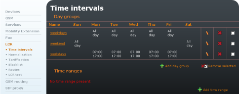 |
Figure 3.56: Time Intervals
Normalising
When we introduced the LCR operations, we mentioned modifications of numbers before input into and after output from the routing process – so-called normalising. Normalising means conditioned transformations of the called and/or calling numbers into a unified format, which facilitates definition of the routing rules. The normalising regulation is determined by the following three parameters
- Normalising type – Define at which process stage (input/output) and for which numbers (called/calling) normalising should be used.
- Condition – Transformation is only applied to numbers that meet a condition. The condition is specified by a prefix – a string that the number starts with. The prefix is separated automatically and the remaining part of the number is transformed only.
- Transformation regulation – Enable to modify a number by removing a certain number of characters from the number beginning, or adding a new prefix.
 |
Figure 3.57: Normalisation
Use the Add icon to create a new LCR normalising rule. By clicking on it you get a rule defining form.
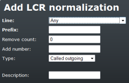 |
Figure 3.58: Normalistaion - Add Rule
The meanings of the fields in the form are identical with the following columns of the normalising table
- Line – Define to which line the rule should be applied.
- Prefix – Prefix that a number must start with to meet the transformation regulation. This prefix is always removed automatically!
- Remove count – Count of characters to be removed from the number beginning behind the prefix.
- Add number – Prefix to be added before the rest of the number after removal of the prefix and a defined count of digits.
- Type – Define at which stage the normalising rules shall be applied. There are four options – Incoming calling – on the calling number input, Incoming called – on the called number input, Outgoing calling – on the calling number output, Outgoing called – on the called number output.
- Description – Any text that describes the meaning of a normalising rule.
Tariff Metering
Call tariff metering (AOC) in the 2N® OfficeRoute/2N® VoiceBlue Enterprise gateways is a sophisticated recording of the called time for each SIM card. Monitoring of free minutes is made with the aim to cut tariff costs and optimise the LCR process. The tariff-metering scheme divides a call into two time ranges. In each range tariff metering can be made according to different time units.
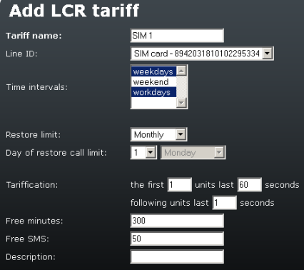 |
Figure 3.59: Add LCR Tariff Form
- Tariff rate name – User defined tariff rate name.
- Line ID – SIM or line to which a tariff rate is applied.
- Time intervals – Time when a tariff rate is applied.
- Restore limit – Time interval of restoring free minutes/SMS
- Day to restore call limit – Specify a day in a month or a day in a week the limit (free minutes/SMS) will be restored.
- Tariff metering – Settings for the counting of used seconds/minutes.
- Free minutes, Free SMS – Count of minutes/SMS to be used during an accounting period (month or day).
Example in Fig. 3.59:
The tariff rate is applied to SIM card 89.......334, only during weekdays and workdays (as defined in the Time intervals parameter). The limit is restored on the 1st day of each month (at a time as set in the unit). Accounting is made as follows – The first 60 seconds of the call are charged immediately. When first 60 seconds elapse, each second is charged.The SIM card can be used for 300 outgoing minutes and 50 sent SMS messages per month. After the call limit is exceeded, no more outgoing calls may be made.
Blacklist
After output normalising and before switching the call to the found output line, the list of barred numbers (blacklist) is checked. If the number begins with a string included in the list the call is rejected. The list includes both whole telephone numbers and/or their initial parts (prefixes) only. Thus, e.g. all international calls or specially rated calls (erotic lines etc.) can be barred.
To adjust the barred numbers use the LCR menu in the group configuration tag. Select the blacklist item to display the list of barred numbers.
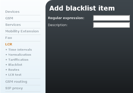 |
Figure 3.60: Blacklist
- Regular expression – Initial part of the barred number (or a whole number).
- Description – Any text that describes the meaning of an item.
Routes
This window includes the list of existing routes and the route adding and removing options. A route means an outgoing trunk (bundle of SIMs, modules, SIP lines or DISA lines).
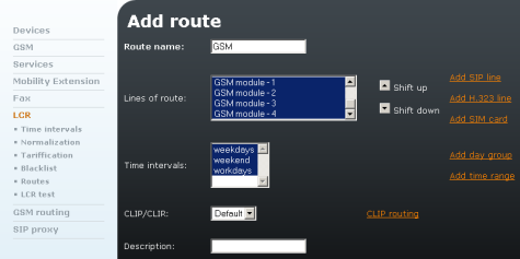 |
Figure 3.61: LCR Routes - Add Route Form
There is a route named 'Mobile Networks' in the figure above, which contains all GSM modules. It is used at all defined time intervals without CLI restriction (CLIR may be used for mobile networks only).
The form contains the following fields
- Route name – The route name may contain any alphanumerical characters. Refer to the LCR rules in the preceding section.
- Lines of route – List of available lines that form a group. To select/remove a line click on the respective item with the left-hand mouse button. You can select more list items at the same time by pushing the CTRL key along with the mouse click. The selected items are illuminated blue.
- Time intervals – Define the routing rule time validity.
- CLIP/CLIR – Enable/disable the caller's identification.
- CLIP routing – Define the CLIP routing table of the route. It contains mappings between CLIP (the calling party number), usually the number of the SIP extension, and single line in the route. If the related route and CLIP routing (as a type of routing) are chosen in a LCR rule, calls will use specific lines according to the CLIP. If you want to put more CLIPs in the same raw, use ";" as a separator. Put a raw with empty CLIP field at the end of the table to route calls when no CLIP match was found (unknown CLIP). Don't create that raw if you want to deny calls with unknown CLIP.
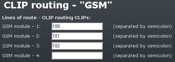 |
Figure 3.62: LCR Route - CLIP routing
- Description – Any text describing the meaning of an item.
LCR Test
The LCR test item in the Least Cost Router (LCR) menu in the Telephony services tag is used for testing changes in the LCR settings. Enter the calling and called numbers and click on the LCR test icon below the form to initiate the LCR process simulation.
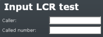 |
Figure 3.63: LCR Test
After simulation, the normalised calling and called numbers plus the name of the successfully found output line or the reason why the line search was unsuccessful are displayed.
GSM Routing
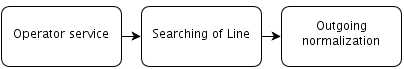 |
Incoming calls from the GSM network are processed by simply being routed to a selected number in the VoIP network. The routing rule may be set for each SIM card of the GSM module separately.
While processing GSM incoming calls, the LCR first tries to find the Operator service according to the GSM module and then according to the SIM card number. After finding the service, it selects the line that is assigned to the Operator service for the incoming call. Finally, the calling number is normalised according to the normalising table.
Operator
To set routing click on the GSM routing reference. The Operator service must be set first. Click on the Operator item to display the table of available operators (see Fig. 3.64).
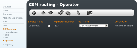 |
Figure 3.64: GSM Routing - Operator
To add an Operator service click on the Add button. This displays the Operator service adding form (see Fig. 3.65).
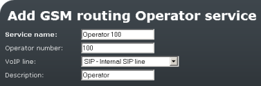 |
Figure 3.65: GSM Routing - GSM Routing Operatior Adding Form
- Service name – The field may contain any alphanumerical characters.
- Operator number – VoIP network number to which the incoming GSM call is routed.
- VoIP Line – Line used for dialling the VoIP network number (also a DISA line).
- Description – Any text describing the meaning of the operator service.
To change the Operator service select the relevant line and click on the Modify button. From now on follow the same steps as mentioned above with the exception that to save the changes click on the Modify item.
To remove an Operator service, select the relevant line (as mentioned above) and click on Remove.
SIM
Click on the SIM item in the menu to the left to display the list of SIM routing rules (see Fig. 3.66).
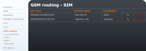 |
Figure 3.66: GSM Routing - SIM Card Routing
Click on the Add routing of SIM card item to display the routing rule adding form (see Fig. 3.67).
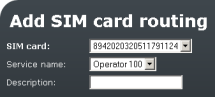 |
Figure 3.67: GSM Routing - SIM Card Routing Adding Form
- SIM card – Select the SIM card number in this field. The incoming calls through the SIM number will be assigned to the service selected in the Service name field.
- Service name – Operator service through which the calls are to be routed into the VoIP network.
- Description – Any text describing the SIM routing rule meaning.
Caution
- If the GSM routing rule is set together with the SIM rules (see later), the GSM rule has a higher priority.
GSM
Click on the GSM item in the menu to the left to display the list of GSM routing rules.
 |
Figure 3.68: GSM Routing - GSM
Click on the Add routing of GSM device item to display the routing rule adding rule (Fig. 3.69).
 |
Figure 3.69: GSM Routing - GSM Module Routing Rule
- GSM device – Enter the GSM module number. The incoming calls through this module will be assigned to the service specified in the Service name field.
- Service name – Service through which the calls are to be routed into the VoIP network.
- Description – Any text describing the GSM routing rule meaning.
GSM Routing Normalising
The table normalises the calling (CLIP) numbers of the incoming calls from GSM network.
The normalisation should be made to display the calling number on the IP telephone in such manner, which enables proper routing of the back call into the 2N® Office Route gateway.
If, e.g., the gateway is configured to dial the calls into the GSM network by means of prefix 0 and the incoming CLIP from GSM network starts with +420, the prefix +420 must be detached and replaced by 0 (see Fig. 3.70).
Example:
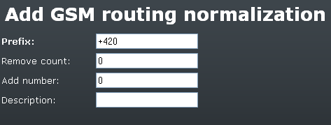 |
Figure 3.70: GSM Routing - Normalising Adding Form
SIP Proxy
IP phones are registered to the internal SIP proxy. The SIP proxy serves as a registrar and location server and also as an RTP proxy for outgoing SIP proxy calls (e.g. calls to a SIP operator).
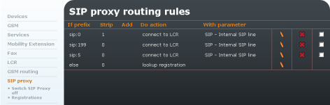 |
Figure 3.71: SIP Proixy Main Screen
Fig. 3.71 shows an example of a completed routing table that gets displayed when you open the SIP proxy item. Each row represents one rule. Having received a call-establishing request, the SIP proxy searches this table from top to bottom for the appropriate routing rule.
Doing this, it compares the called destination with the value in the first table column. If the called subscriber's identifier starts with the prefix included in the If prefix field of the routing rule, the SIP proxy terminates searching and uses the rule found.
The last table row represents the so-called initial routing rule. It cannot be deleted. It is applied to all calls for which no explicit routing rule has been found. The routing rule defines what the SIP proxy should do with a call. It can reject it, forward it to another host and/or port, transfer it to a gateway VoIP line (i.e. to the LCR), or search for the called subscriber in the database of logged-in SIP telephones. Before one of the above mentioned operations is executed, it is possible to modify the called subscriber's identifier by removing a certain number of characters from the left or adding a new string to its beginning (refer to the Remove and Add columns).
The SIP proxy routing rules define routing (according the prefix of the dialled number). There are 2 rules by default - all dialled numbers with prefix 0 are routed to the internal SIP line and the remaining are to be looked up for registered IP phones.
Add rule
There is an Add rule icon below the table too. Click on it to display the rule defining form. Fig. 3.72 shows a form for setting the SIP proxy routing rules. The form fields correspond to the header of the table in Fig. 3.71.
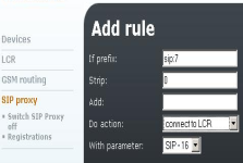 |
Figure 3.72: Proxy Routing Rule Adding Form
The form and the table include the following fields
- If prefix – If the called subscriber's URI (Uniform Resource Identifier) starts with this string, this rule is used for routing. In the SIP environment, the URI is introduced with the "sip:" prefix, which must be included in the value in this field.
- Strip – Number of characters following the "sip:" prefix to be removed from the URI before processing.
- Add – String to be inserted in the URI behind the "sip:" prefix.
- Do action – Define what to do with a call. There are six potential actions in the pop-up menu but, in principle, there are only three of them – rejection, forwarding and connecting within the SIP proxy registrations. However, let us mention all the options briefly to have a full picture:
- Reject – the called line gets the busy tone;
- Rewrite host – forwards the call to the same port of the selected host;
- Rewrite port – forwards the call to the selected port of the same host (this can have the same effect as option 5);
- Rewrite host and port – forwards the call to any port of the selected host;
- Connect to LCR – connects the call to the selected gateway SIP line and thus to the LCR; and finally
- Lookup registration – tries to search the SIP proxy registered users for the required URI and forward the call to the appropriate host.
- With parameter – The above actions, except for the first and last ones, require a parameter to be set. This parameter is a new routing destination for call forwarding and the SIP line name for the Connection to 2N® OfficeRoute action.
In the figure - routing is done according to the prefix. The action might be Connect to LCR, Reject, Change host and port and Lookup registration. The parameter means here the routing destination of a call. There is a significant difference against the Normalising table – the prefix is not removed in the proxy rule.
Switch SIP Proxy Off
The proxy may be switched off when the unit is used as a UMTS router only.
If the integrated SIP proxy server is switched on, it may be switched off by clicking on the Switch SIP Proxy off menu item.
If the SIP proxy server is switched off, it may be switched on by clicking on Switch SIP Proxy on menu item.
Registrations
It is possible to monitor via the web interface which equipment units are registered at the SIP proxy.