3.4 Network Settings
Main Configuration
Includes 2N® OfficeRoute own IP address, mask, default gateway and DNS. There is also a possibility to switch on the DHCP client (when 2N® OfficeRoute does not serve as a DHCP server and there is another DHCP server in the network). It is also possible to select the main settings via a serial console or a Telnet console.
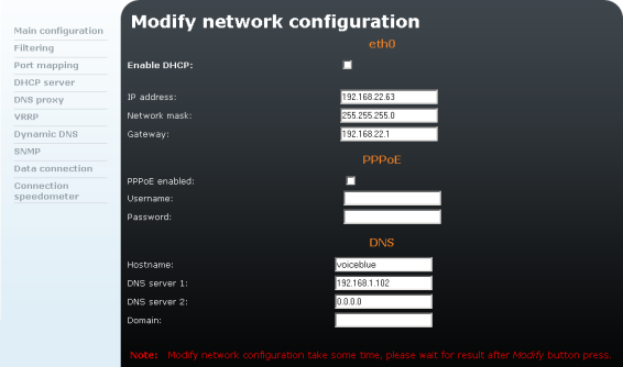 |
Figure 3.14: Main Configuration
The form includes the following items:
- Enable DHCP – Select whether the network parameters should be obtained from the DHCP server, or whether they should be set manually.
- IP address – Set the IP address of the device. If Dynamic address allocation via DHCP is enabled, the value cannot be changed manually.
- Network mask – Set the network mask. If Dynamic address allocation via DHCP is enabled, the value cannot be changed manually.
- Gateway – Set the IP address of the default router. Used for data traffic routing beyond the network limits. If dynamic address allocation via DHCP is enabled, the value cannot be changed manually.
- PPPoE enabled – Enable/disable connection via the PPPoE protocol. The User name and Password help identify the user.
- DNS1 – Set the IP address of the first DNS.
- DNS2 – Set the IP address of the second DNS.
Click on Modify to confirm the changes. Setting new values takes some time; please wait for the browser response.
Filtering
Embedded firewall settings. To add a new rule, click on the  icon. It is possible to set a rule for call accepting/barring according to the type of traffic, source or destination IP address or port. While creating more rules than one remember that these rules are searched from top to bottom.
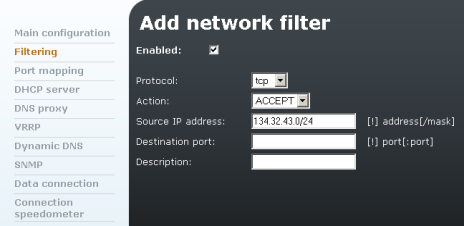 |
Figure 3.15: Filtering
The form in Fig. 3.15 contains the following fields:
- Protocol – Protocol to be filtered.
- Action – You can accept or drop packets that are filtered.
- Source IP address – IP address to be filtered.
- Destination port – Destination port to be filtered.
- Description – Provides information on the rule.
Port Mapping
NATP setting for access devices in an internal LAN via the UMTS network (a public IP must be assigned to 2N® OfficeRoute by the provider). It is a transparent process where the network clients cannot see that port forwarding is being done. This process enables you to run a public Internet service on a machine that is otherwise hidden from the Internet by your gateway.
Example:
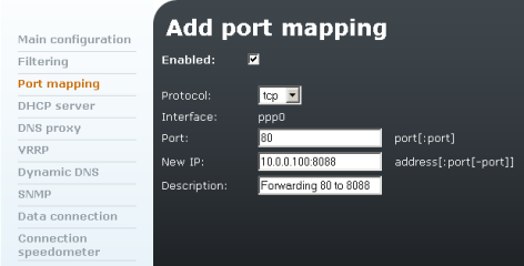 |
Figure 3.16: Port Mapping
The configuration shown in Fig. 3.16 enables you to create a permanent translation entry that maps a TCP port 80 on your gateway to an IP address 10.0.0.100 and port 8088 on your private LAN.
DHCP Server
DHCP server settings in case 2N® OfficeRoute serves as a LAN DHCP server.
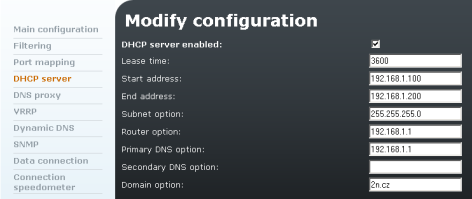 |
Figure 3.17: DHCP Server Settings Form
- Lease time – Validity of a leased IP address in seconds.
- Start address – Start of an IP address pool.
- End address – End of an IP address pool.
- Subnet option – Subnet mask for an internal network.
- Router option – Default gateway of subnet (typically the 2N® OfficeRoute IP address, for VRRP it is the IP address of the virtual router.
- Primary / Secondary DNS – Used only in the case of local DNSs in the LAN.
DNS Proxy
Used for caching DNS records in case 2N® OfficeRoute works as a UMTS/GPRS router. The DSN proxy can receive DNS queries from the local network and forward them to an Internet Domain Name Server. If the DNS Proxy is disabled, the gateway forwards all requests to the servers assigned by the UMTS 2N® OfficeRoute provider.
The gateway can use the DNSs from the Network settings or you can forward the DNS queries to specified servers.
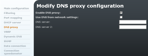 |
Figure 3.18: DNS Proxy Configuration
VRRP
The Virtual Router Redundancy Protocol is an Internet protocol, which provides a possibility to have one or more backup routers when using a statically configured router on a local area network (LAN). The most common arrangement is to specify one router to serve as the router for forwarding packets from a group of hosts on a LAN. If the router fails, however, there is no way to use another router as a backup.
Using VRRP, a virtual IP address can be specified manually or with the Dynamic Host Configuration Protocol (DHCP) by default. A virtual IP address is shared by the routers, with one designated as the master and the others as backups. In case the master fails, the virtual IP address is mapped to the backup router IP address (this backup thus becomes the master router). If the backup router becomes master, the default gateway to the PSTN is set automatically. If this new master becomes a backup router again, the default gateway to LAN (Ethernet interface) is recovered.
| Figure 3.19: VRRP Configuration |
- VRID – Provides virtual router identification. Must be unique for each virtual router.
- Priority – The higher the number, the lower the priority.
- Advertisement interval – Set the time interval (in seconds) between advertisements. The default value is 1 second. This field is used for troubleshooting of misconfigured routers.
- Virtual router address – Set the IP address of a virtual router.
Dynamic DNS
The DDNS provides a gateway that has a variable, often changing IP address with a well-known hostname resolvable by network applications through standard DNS queries.
An example of use is a home user who wishes to access the computer on his or her home network while travelling. The user may be supplied with a different IP address whenever the Internet connection to the service provider is made, so there is no stable address to connect to. If the Dynamic DNS service is used to assign a fixed address to the device, then the user can, for example, establish a Virtual Private Network (VPN) to the network using that address. As a detailed example, the IP address can be 123.234.111.112 one day, 123.124.45.15 the next, but the Dynamic DNS address will always be, e.g. - office-route.dyndns.org.
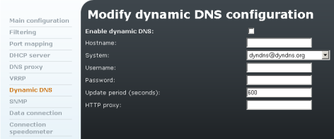 |
Figure 3.20: Dynamic DNS Configuration
- Hostname – Your hostname registered with a DDNS provider.
- System – Choose your DDNS provider from the list of supported DDNS providers.
- Username – Enter your username in accordance with your DDNS account.
- Password – Enter your password in accordance with your DDNS account.
- Update period – Period of IP address updating at the DDNS server.
- HTTP proxy – Enter the IP address of your HTTP proxy. If you have no HTTP proxy, leave the field blank.
SNMP
The Simple Network Management Protocol (SNMP) daemon is a background server process that can be run on any Transmission Control Protocol/Internet Protocol (TCP/IP) workstation host. It helps you monitor the state of the device on the network.
2N® OfficeRoute is capable of receiving and responding to requests sent by SNMP versions v1 and v2c. SNMP traps-messages on events to be notified-are sent by SNMP v2c by default.
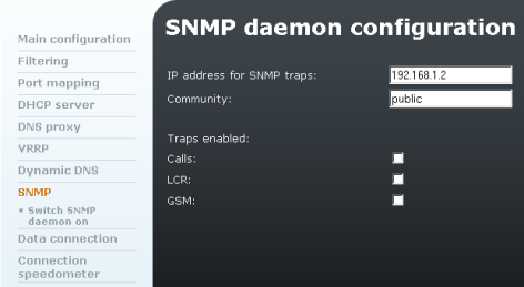 |
Figure 3.21: SNMP Configuration
- IP address for SNMP traps – The IP address to which traps are sent. Port 162 is used for communication by default. If necessary, set another port behind the IP address colon (192.168.1.2:163, e.g.).
- Community –The group to which the devices and management stations running via SNMP belong. Helps you can define where information shall be sent. The default SNMP communities are:
- Write – private
- Read – public
- Traps enabled –Enable following traps for:
- Calls
- Dialing new call.
- Call connected.
- Call hang up.
- LCR
- LCR failed - no LCR path, all lines busy or blacklisted call.
- GSM
- SIM card inserted or removed.
- GSM network registration.
- GSM module doesn't respond to ATD command.
- GSM module respond ERROR to ATD command.
- Calls
Data Connection
In this menu you can see the list of inserted SIM cards and start/stop data connection by clicking on Connect/Disconnect.
Note
- If there is no SIM card in the data connection list:
1. Make sure that the SIM card has been inserted in the device and logged in.
2. Check the Data connection settings for the SIM card-see later.
3. Click on the  icon in the right-hand bottom corner to re-read the page.
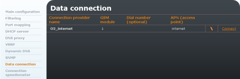 |
Figure 3.22: Data Connection - SIM Cards
Modification of SIM Card Parameters
To modify the data connection settings click on the pencil icon.
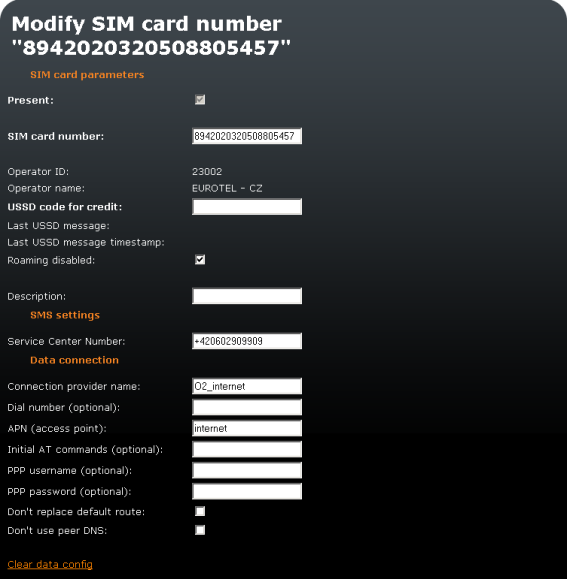 |
Figure 3.23: Data Connection - Modify SIM Card Form
Note
- You are strongly recommended to power off the unit before inserting/removing the SIM card
Modification of SIM card parameters:
- Present – Checkbox indicates whether the SIM is present in the tray at the moment.
- SIM card number – Information on the SIM serial number (IMSI).
- Provider ID – Provider's network code.
- Provider name – Provider´s name.
- USSD code for credit – Fill in the USSD code for credit check for your prepaid SIM cards. If you fill in the proper USSD code and the SIM card is prepaid, you can obtain credit information by clicking on Get credit in the SIM cards list.
- Last USSD message – Shows the last obtained USSD message.
- Last USSD message time stamp – Shows the last USSD message timestamp.
- Roaming disabled – Disable/enable roaming for the given SIM card. Roaming is disabled for new SIM cards by default and has to be enabled if necessary.
- Description – User description of the SIM card.
- Service Centre Number – Enter the service centre number. It is necessary for SMS sending.
- Connection provider name – Enter any name. This field is compulsory.
- Dial number (optional) – Number to be dialled for data connection
- APN (access point) – This field is compulsory. Complete it in accordance with your provider´s APN name.
- Initial AT commands (optional) – Optional field. You can define here a special AT command for Internet connection.
- PPP username (optional) – Optional field. Enter your PPP user name if it is recommended.
- PPP password (optional) – Optional field. Enter your PPP password if it is recommended.
- Don't replace default route – Tick off this item to leave the default gateway set to LAN (Eth interface) after data connection is established. Make changes with the data connection off.
- Don't use peer DNS – Define whether the DNS IP addresses should be overwritten in compliance with the data connection provider after data connection is established.
In order to use the SIM for data/Internet connection (for GPRS/EDGE/UMTS/HSPA) you have to set the Connection provider name and APN parameters. The other parameters depend on the network provider's data. To obtain the data, refer to your network provider's websites or call the provider's helpline.
Connection Speedometer
This section shows the data receiving (download) and sending (upload) rate, the currently used data transmission technology and the signal intensity value for each module.
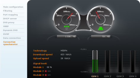 |
Figure 3.24: Connection Speedometer
Two speedometers are displayed: the one on the right shows the download rate and the one on the left the upload rate. The counter below the indicators displays the count of received or sent data since the last connection.