2N® Net Audio Decoder mono PCB
 |
2N® Net Audio Decoder mono PCB, Part No. 914050E
Accessories:
- 12 V / 2 A DC adapter, Part No. 914102x (E – Europe, GB – Great Britain, US – USA)
Product Description
The 2N® Net Audio Decoder mono PCB is a LAN audio converter designed for public sound distribution through the 2N IP Audio System system. It is connected to the 2N IP Audio System via the local area network (LAN). It communicates with the 2N® IP Audio Manager, receives the audio stream, decodes it and converts it into an analogue signal. The 2N® Net Audio Decoder mono PCB can be controlled by two front buttons or an infrared remote controller. The 2N® Net Audio Decoder mono PCB is equipped with a digital input and output, which extend the converter options and may be helpful in special applications.
The 2N® Net Audio Decoder mono PCB helps you extend the internal FLASH memory using microSD memory cards. Apply the 2N IP Audio System software for configuration and use of all functions (refer to the 2N® Net Audio Decoder Quick Start and 2N IP Audio Administration manuals for more details).
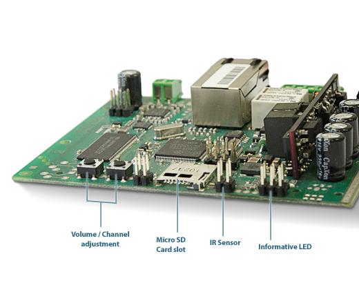 |
2N® Net Audio Decoder mono PCB Front View
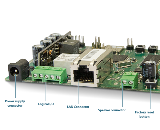 |
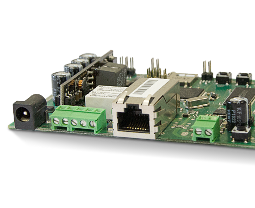
2N® Net Audio Decoder mono PCB Back View
2N® Net Audio Decoder mono PCB Parameters
Parameter | Value |
|---|---|
Board dimensions | 100 x 80 x 15 mm |
External power supply | 12 V DC / 2 A |
LAN supply | not supported |
Status signalling | LED at the front |
Local control | 2 buttons at the front |
Remote control | infrared sensor at the front |
Headphone/Line output | 3.5mm stereo jack at the front |
LAN connection | RJ-45 connector at the back, TX with Auto-MDIX function |
Power amplifier output | not supported |
| Line output | speaker connector at the back |
| Type loudspeaker | 8 Ω / 6 W |
Frequency range | 20 Hz – 20 kHz (+/– 0.5 dB) |
Harmonic distortion | 0.05 % @ 1 kHz |
Signal–to–noise ratio | 91 dB |
Digital output | 24 V 1 A AC/DC relay output, galvanically isolated |
Digital input | 5 to 24 V DC digital input, galvanically non-isolated |
External memory | microSD card slot at the front |
Sound compression | MPEG-1 Audio Layer II (MP2) |
Bandwidth | 32–320 kbps |
Caution
- Be sure to connect the 2N® Net Audio Decoder mono PCB power supply as the last step.
Installation
View of the 2N® Net Audio Decoder mono PCB inputs/outputs:
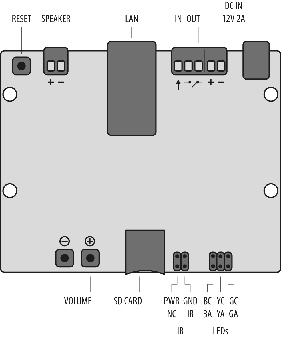 |
Description of 2N® Net Audio Decoder mono PCB Connectors and Motherboard Inputs
- 12 V / 2 A DC power supply adapter connector
- Alternative power supply connection terminals
- Relay output with galvanic isolation for external 24 V / 1 A AC/DC load switching
- Digital input 5–24 V (without galvanic isolation) for external sensor/button, etc.
- 10/100BASE-TX LAN RJ-45 connector
- RESET button
- Universal buttons with programmable functions (volume/channel)
- MicroSD card slot for higher internal memory capacity
- Infrared signal receiver for remote control
- Operational status colour LED indicator
Caution
You are advised to make the Reset button accessible to the user for factory reset.
Mounting Hole Spacing and Motherboard Size
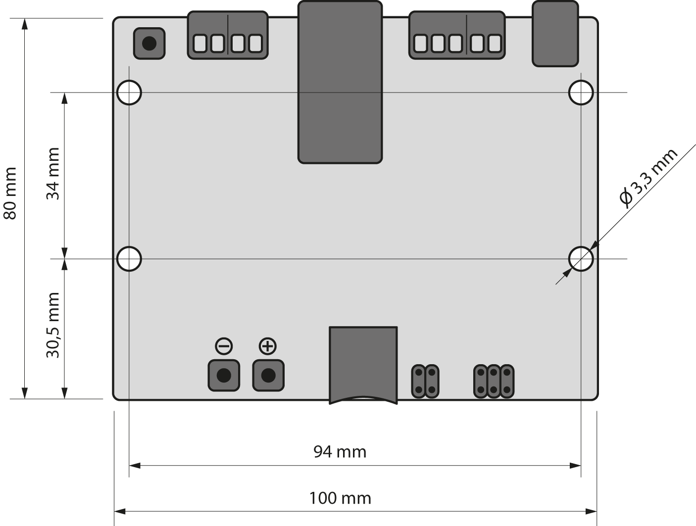 |
2N® Net Audio Decoder mono PCB Mounting Hole Spacing and Motherboard Size
Electric Installation
It is very easy to connect 2N® Net Audio Decoder mono PCB electrically. Follow the steps below to avoid equipment damage or electrical injury:
Connect an 8 Ω / 6 W speaker.
Connect the digital input and output.
Insert the microSD card.
Connect a UTP cable with PoE, or a UTP cable and a 12 V power supply.
Digital Input and Output
The 2N® Net Audio Decoder mono PCB is equipped with a relay switch for light signalling/external amplifier/alarm/activation. The output is available on terminals marked LOGIC OUT and allows for switching of up to 24 V / 1 A AC/DC loads. The relay is controlled by the audio stream sent to the 2N® Net Audio Decoder Lite PCB.
Warning:
Do not exceed the upper voltage and current limits to avoid irreversible damage of the equipment.
The 2N® Net Audio Decoder mono PCB is equipped with a digital input for an optional button, sensor of movement or other applications. This input is available on the LOGIC IN terminal. 5 to 24 V DC voltage can be applied to the input against the ground terminal marked DC IN-. In the case of external button, the DC IN+ terminal can be used; see the figure below.
Warning:
Do not exceed the maximum voltage values (24 V) applied to the LOGIC IN input to avoid irreversible damage of the equipment.
Memory Card
The 2N® Net Audio Decoder mono PCB is equipped with a microSD card slot for storing music or voice in case the equipment is not connected to the LAN permanently or temporarily. The microSD card slot is available at the 2N® Net Audio Decoder mono PCB front.
Status LED Indicators
LED colour | LED status | Meaning |
|---|---|---|
| Yellow | shining | 2N® Net Audio Decoder mono PCB is booting or restarting |
| Green | shining | 2N® Net Audio Decoder mono PCB is playing audio from 2N® IP Audio Manager |
| Violet | shining | 2N® Net Audio Decoder mono PCB is playing audio from SD card |
| Violet | flashing | 2N® Net Audio Decoder mono PCB načítá SD kartu |
| Green | flashing slowly 3 times | 2N® Net Audio Decoder mono PCB úspěšne načetl SD kartu |
| Blue | flashing | 2N® Net Audio Decoder mono PCB is ready, but not connected to server |
| Blue | shining | 2N® Net Audio Decoder mono PCB is ready and connected to server |
| Yellow | flashing | 2N® Net Audio Decoder mono PCB is upgrading or starting from default after factory reset |
| Orange | flashing fast | Volume + / - / infra |
| Orange | flashing slowly 3 times | Blink |
| Orange | shining | 2N® Net Audio Decoder is in MUTE state |
Power and Connection
The mono PCB can be connected to a standard local area network using a LAN interface via the RJ-45 connector on the backside. Always use CAT-5d or higher class cables for reliability reasons. The LAN interface is equipped with the Auto MDIX function for automatic detection of a straight or cross–over cable.
The 2N® Net Audio Decoder mono PCB can be fed using a 12 V / 2 A DC (Part No. 914102E) power supply, or another power supply on condition that you keep the nominal values included in the Electric Parameters subsection.
Connect the 12 V DC power supply either to the backside supply connector marked DC IN, or terminals marked DC IN+ and DC IN-.
Warning:
If you use an adapter other than the recommended one, do not exceed the nominal supply voltage value of 12V. Also make sure that the supply voltage polarity is correct. Exceeding nominal values and/or incorrect connection may lead to irreversible damage of the equipment.
2N® Net Audio Decoder mono PCB Factory Reset
In some cases, it may be useful to reset the 2N® Net Audio Decoder mono PCB factory values using the RESET button on the backside. Do this, for example, if the 2N® Net Audio Decoder mono PCB ceases to respond, which may be caused by incorrect LAN settings, LAN configuration changes, forgotten password and so on.
Resetting Procedure:
- Use a thin rigid tool to press the RESET button on the back panel.
- Keep the RESET button pressed (for approx. 15 s).
- Release the button as soon as the LED starts shining violet.
This operation takes about 50 s. Do not disconnect the device from power supply during this period.
Firmware Upgrade
The firmware upgrade starts automatically whenever the 2N® Net Audio Decoder mono PCB gets connected to the 2N® IP Audio Manager. This guarantees that all connected devices have identical and latest firmware versions. Refer to www.2n.cz for the latest firmware version.
Operating Terms and Transport
Operating temperature: 0 to 40 °C (32 to 104 °F)
Operating humidity: 10 to 85 % (not condensing)
Permitted temperature range for product transport: -25 to +60 °C (-13 to 140 °F)