2.5 Audio Unit - Lift Shaft - Cabin Roof
Description
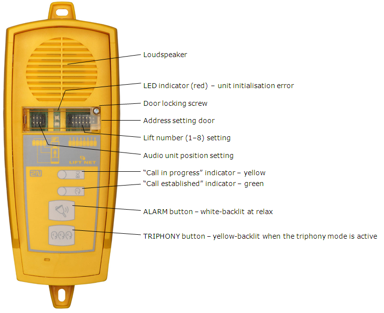
This audio unit is designed for installation on the lift shaft bottom or lift cabin roof, or similar places where communication is needed during lift maintenance, for example. The audio unit is enclosed in a robust yellow cover. It is not intended for outdoor use but perfectly fits in lift shafts – is resistant against fall of small objects, dripping oil, etc. The ALARM button activates the dispatching centre connection, the TRIPHONY bottom enables conference connection with the other audio units of one and the same lift. The audio unit contains a built-in microphone and a loudspeaker. Thanks to its size and robustness, the audio unit features a very good sound.
 |
Operating instructions
This unit may only be used by authorised persons such as the lift maintenance staff.
The TRIPHONY button activates voice communication between all units with the same lift number.
The ALARM button can be used, for example, when somebody falls into the shaft. The ALARM button backlight (not required by standards) allows you to find the unit in a dark environment.
Before You Start
Product completeness check
Check the product for completeness before installation please:
- 1 audio unit
- 2 wall dowels
- 2 dowel screws
Requirements
There are no special requirements for this unit type.
Caution
- This audio unit is not designed for lift cabins.
Mounting
Typically, the audio unit is mounted onto a wall using the dowels and screws included in the delivery. Find the drilling pattern on the product package.
Caution
- The audio unit is not designed for outdoor applications.
Electric Installation
Connectors
This unit has only one connector (bus) under the side door.
Address setting
The audio unit address means setting of two jumpers, namely the lift number (1 to 8) and audio unit position (refer to the cover drawing). If you install the audio unit on the shaft bottom of lift 1, you need not change the jumper configuration. Otherwise, follow the instructions below:
Instructions
- Release the screw on the jumper window cover and open the window.
- Configure the required changes as printed below the window (this audio unit cannot be shared by multiple lifts).
- Close the window and tighten the screw.
Warning
- Avoid the audio unit address duplicity.
Connection
Relase the screw on the right-hand side and open the connector cover. There is just one connector – for bus connection. Remove the terminal board from the connector, connect the wires and replace the terminal board. The connection polarity is arbitrary.
Warning
- Connection to different, e.g. higher-voltage, cables leads to damage or destruction of the audio unit.
Caution
- The unit is powered via a 2-wire bus from the central unit. Unplugging of the bus from the CU causes switching off of the unit.