3.2 Programming Function Overview
The tables below include all the programming functions.
Table of Parameters
Par. No. | Parameter name | Range of values | Default value | Note | |
|---|---|---|---|---|---|
011 | ALARM button memory 1 | up to 30 digits: 0–9 | empty | Enter Direct SIP (calling without Proxy server)
| |
012 | ALARM button memory 2 | up to 30 digits: 0–9 | empty | ||
013 | ALARM button memory 3 | up to 30 digits: 0–9 | empty | ||
014 | ALARM button memory 4 | up to 30 digits: 0–9 | empty | ||
015 | ALARM button memory 5 | up to 30 digits: 0–9 | empty | ||
016 | ALARM button memory 6 | up to 30 digits: 0–9 | empty | ||
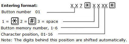
017 | Enter special character into alarm call memory |
| |||
| 018 | Count of automatic dialling cycles for ALARM | 0–9 | 3 | If 0 is set, only the first number in the memory is called regardless of the count of stored numbers.
| |
| 111–116 | Set 1 - Alarm call memory 1–6 confirmation mode (set 1) | 1–9 | 1 | 1 = with DTMF confirmation (1) 2 = with pick-up confirmation (for GSM/UMTS/VoIP only) 3 = CPC Antenna 4 = CPC Kone 5 = P100 6 = DTMF auto detection (CPC Antenna/P100) 7 = CPC Antenna 2N ext 8 = CPC Kone 2N ext 9 = P100 2N ext The 2N ext protocol transmits identification including the shaft number and audio unit position (for 2N Lift8 communicator display). Unless a troublefree DTMF transmission is secured, specify the protocol to be used (3 or 5) rather than set 6 for CPC Antenna/P100 auto detection.
| |
| 021 | Set 2 – ALARM 2 button memory 1 | up to 30 digits: 0–9 | Entering characters If the memory set 2 for Alarm 2 is completely empty, no fall to the first memory set for ALARM occurs. The Alarm 2 button is on the IO extender. | ||
| 022 | Set 2 – ALARM 2 button memory 2 | up to 30 digits: 0–9 | |||
| 023 | Set 2 – ALARM 2 button memory 3 | up to 30 digits: 0–9 | |||
| 024 | Set 2 – ALARM 2 button memory 4 | up to 30 digits: 0–9 | |||
| 025 | Set 2 – ALARM 2 button memory 5 | up to 30 digits: 0–9 | |||
| 026 | Set 2 – ALARM 2 button memory 6 | up to 30 digits: 0–9 | |||
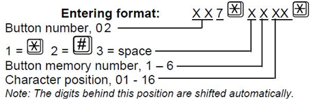
| 027 | Insert specific character in ALARM 2 memory set 2 |
| |||
| 028 | Set 2 – count of automatic dialling cycles for ALARM | 0–9 | If 0 is configured, only the first number in the memory is called regardless of the count of saved numbers.
| ||
| 121 – 126 | Set 2 – number 1-6 confirmation mode | 1–6 | 1 | 1 = with confirmation DTMF (1), If there is no guarantee of problem-free transfer of DTMF, do not set 6 for autodetection CPC Antenna/P100, but precisely specify the protocol to be used (3 or 5). | |
071 | Check call memory 1 | up to 30 digits: 0–9 | empty | Enter Caution: Remember to set the check call number that routes the call to the 2N® Lift8 server. With the fall to sets 011–016, the call may not be confirmed properly. | |
072 | Check call memory 2 | up to 30 digits: 0–9 | empty | ||
073 | Check call memory 3 | up to 30 digits: 0–9 | empty | ||
074 | Check call memory 4 | up to 30 digits: 0–9 | empty | ||
075 | Check call memory 5 | up to 30 digits: 0–9 | empty | ||
076 | Check call memory 6 | up to 30 digits: 0–9 | empty | ||
077 | Enter special character into check call memory |
| |||
| 078 | Count of automatic dialling cycles for check calls | 0–9 | 3 | If 0 is set, only the first number in the memory is called regardless of the count of stored numbers. | |
| 171–176 | Check call memory 1–6 confirmation mode | 1–6 | 1 | 1 = with DTMF confirmation (1) 2 = with pick-up confirmation (for GSM/UMTS/VoIP only) 3 = CPC Antenna 4 = CPC Kone 5 = P100 6 = DTMF auto detection (CPC Antenna/P100) Unless a troublefree DTMF transmission is secured, specify the protocol to be used (3 or 5) rather than set 6 for CPC Antenna/P100 auto detection. | |
| 081 | Operational call memory 1 | up to 30 digits: 0–9 | empty |
Enter Caution: Remember to set the operational call number that routes the call to the 2N® Lift8 server. With the fall to sets 011–016, the call may not be confirmed properly.
| |
| 082 | Operational call memory 2 | up to 30 digits: 0–9 | empty | ||
| 083 | Operational call memory 3 | up to 30 digits: 0–9 | empty | ||
| 084 | Operational call memory 4 | up to 30 digits: 0–9 | empty | ||
| 085 | Operational call memory 5 | up to 30 digits: 0–9 | empty | ||
| 086 | Operational call memory 6 | up to 30 digits: 0–9 | empty | ||
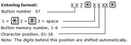
| 087 | Enter special character into Operational call memory |
| |||
| 088 | Count of automatic dialling cycles for Operational call | 0–9 | 3 | ||
| 181–186 | Operational call memory 1–6 confirmation mode | 3–6 | 5 | 3 = CPC Antenna 4 = CPC Kone 5 = P100 6 = DTMF auto detection (CPC Antenna/P100) 7 = CPC Antenna 2N Ext, 8 = CPC KONE 2N Ext, 9 = P100 2N Ext In version 2.4.0 and higher it is used for announcing new events (button repaired, audio repaired). | |
| 800 | Time setting | hhmm | Read the current time; you can edit a new time value. * | ||
| 801 | Date settings | RRMMDD | Read the current date; you can edit a new date value. * | ||
| 810 | Next checking call timeout | hhmmss | The voice menu reads the value in the hours/minutes/seconds (hhhmmss) format. The value defines the next checking call timeout. | ||
| 811 | Manual checking call activation | Click * for confirmation after dialling the service. The checking call is set up the moment programming is completed. | |||
| 890 | CU restart | Re-enter the valid service password. * | |||
| 898 | Cancel work configuration | Cancel the changes made during this configuration call except for the date and time changes! Use an asterisk for confirmation. * | |||
| 899 | Full initialisation (including the service password!) | Enter the valid service password to avoid unintentional deletion in case of function number mistyping). * (Parameters 1100–1110 are not deleted during full initialisation). | |||
912 | Maximum call duration | 15–990 s | 120 s | Use the call extending command (DTMF 4 or *) to extend a call. | |
913 | Login timeout | 10–990 s | 60 s | Set the maximum period of time for the control centre to answer the call and send confirmation, otherwise L1 hangs up and dials the next number. Counted from the end of dialling. | |
914 | Delayed call | 0–100 s | 0 s | Applied only if the CANCEL input is connected. | |
961 | Inter-digit timeout | 5–120 s | 10 s | During password entering | |
962 | Minimum ALARM pressing time in cabin | 100–9999 ms | 5000 ms | Applies to the ALARM button and button 2. | |
| 963 | Minimum button pressing time to trigger forced/test alarm | 0–30 s | 0 s | Set the minimum time in seconds for which the alarm button needs to be pressed to activate the forced/test alarm. This alarm bypasses the cancel contact status. 0 = disabled | |
965 | Privacy mode | 0–24 hours | 0 | Private mode allows muting of the microphone on the car unit 2N® LiftIP. Possible setting of this parameter when the rescue mode is used are: | |
973 | Language for numeric announcements | 0–1 | 1 | 0 = user recorded messages 1 = voice menu language The user recorded digits are played if parameters 975–979 or 971 are set to 11, 12 or 13. | |
974 | Intercom Id | up to 16 digits: 0–9 | empty | Lift identification if there is a foreigner in the lift.
| |
975 | Cabin announcement sequence | up to 10 announcements in succession | empty | Start announcements in multiple languages in a given order. The sequences can include such numeric data as lift number, etc. 01 = user message 1 02 = user message 2 03 = user message 3 04 = user message 4 05 = user message 5 06 = user message 6 07 = user message 7 08 = user message 8 09 = user message 9 10 = user message 10 11 = product number 12 = identification code (reads parameter 974 value) 14 = pause (2 s) 15 = (confirmation tone) Caution User messages #1 through #10 are recorded into the Central Unit via the Service Tools.
| |
976 | Message sequence for the control centre (before confirmation with 1) | up to 10 announcements in succession | empty | ||
977 | Check call sequence | up to 10 announcements in succession | empty | ||
978 | Message sequence after connection confirmation | up to 10 announcements in succession | empty | ||
979 | Message sequence for the control centre after pressing 3 after call confirmation | up to 10 announcements in succession | empty | ||
971 | Sequence for call end | up to 10 announcements in succession | empty | ||
981 | Check call mode | 0–6 | 0 | 0 = disabled 1 = enabled, first call in 3 minutes and then as set in parameter 983 2 = enabled, first call in 2 hours and then as set in parameter 983 3 = enabled, call as set in parameter 983 4 = enabled, call on the nearest day set in parameter 986 5 = enabled, first call in 3 minutes and then as set in parameter 986 6 = enabled, first call in 3 minutes and then as set by the server during the call | |
982 | Check call interval | hhmmhhmm | 00002359 | Set announcements for lower traffic (lower tariff) time, generated at random in the set time interval. | |
983 | Check call period | 0–100 days | 3 days | 0 = disabled (setting of parameter 981 to 0 has the same effect). The value is applied if parameter 981 is set to 1–6. | |
986 | Days of week for check calls | mtwtfss | 0000000 | Values for Mon, Tue, Wed, Thu, Fri, Sat, Sun: 0 = do not call 1 = call Example:
| |
| 987 | LED signalling according to EN 81-28 | 0–1 | 1 | Yellow LED permanently on during an Alarm Call. Yellow and green LED flashing alternately after an unsuccessful checking call. | |
| 990 | Enable operational calls at events | xxxxxxx | 0000000 | The value sets whether or not the operational call shall be triggered at events. Each digit enables (1) or disables (0) calls at actions in the following order: Rescue end, Button stuck, Button unstuck, Audio error, Audio fixed. Do not use in combination with event scripts! | |
991 | Service password | up to 16 digits: 0–9 | 12345 | Change the default programming password for access to the programming mode via a voice menu and for full initialisation. | |
| 992 | Rescue password | up to 16 digits: 0–9 | empty | Set the rescue process terminating password. | |
| 993 | Enable automatic audio unit test | 0–1 | 0 | 0 = disabled 1 = carry out an audio test of the audio units after the check call. | |
1100 | Enable DHCP client | 0–1 | 1 | The DHCP server assigns the following to the devices via DHCP: IP address, network mask, default gateway and the address of the DNS server.** 0 = disabled 1 = enabled | |
| 1101 | IP address | empty | IP address assigned to the Ethernet interface (VoIP module). ** | ||
| 1102 | Subnet mask | empty | Gives the subnet bit mask. ** | ||
| 1103 | Default gateway | empty | Sets the IP address of the router or PC via which communication is made outside the internal network. ** | ||
| 1104 | DNS server | empty | Represents the IP address of the DNS server. ** | ||
| 1105 | SIP server | empty | Represents the IP address for login to the counterparty (PBX, operator). ** | ||
| 1106 | User | up to 64 characters | empty | Represents the user name for login to the counterparty (PBX, operator). ** | |
| 1107 | Password | up to 32 characters | empty | Represents the password for login to the counterparty (PBX, operator). ** | |
| 1108 | Enable in-band DTMF detector | 0–1 | 0 | If you enable an in-band DTMF detector, all others DTMF detectors will be disabled.** | |
| 1109 | SIP server port | 1–65535 | 5060 | Represents the PBX (operator) port via which the SIP Proxy communicates with the terminals connected. ** | |
| 1110 | Registration validity | 0–3600 s | 0 s | 0 = registration validity not sent (assigned by the counterparty)** | |
| 1111 | Authentication name | empty | Set the name used for authentication. | ||
| 1112 | Display name | empty | Set the name displayed on the peers device. Use #A to generate the calling unit address, #S to generate the calling unit shaft. | ||
| 1113 | Domain | empty | If the domain is not set, the registrar is used instead. | ||
| 1114 | Outgoing proxy | empty | Outgoing proxy address. The registrar address is used, if not set. | ||
| 1115 | Outgoing proxy port | 1-65535 | 5060 | Outgoing proxy port. The registrar port is used, if the outgoing proxy is not set. | |
| 1120 | RTSP server | empty | IP camera RTSP address (H.264) (e.g. AXIS rtsp://192.168.1.100/onvif-media/media.amp) | ||
| 1121 | Username | empty | IP camera login user name | ||
| 1122 | Password | empty | IP camera login password | ||
| 1150 | Time zone | -12–12 | 1 | Set the time zone (UTC) in which 2N® LiftIP is installed. | |
| 1151 | Synchronisation period | 60–86400 s | 3600 s | Set how often 2N® LiftIP shall synchronise with the SNTP server. ** | |
| 1160 | SNTP on | 0–1 | 0 | Enable SNTP synchronisation. ** 0 = disabled 1 = enabled | |
| 1161 | SNTP server 1 address | 212.51.144.44 | ** | ||
| 1162 | SNTP server 2 address | 81.95.103.173 | ** | ||
| 1230 | Client enabled | 0–1 | 0 | Data client enable (refer to the 2N® Lift8 manual, Subs. 7.1 Control Panel) ** | |
| 1231 | Server IP address | empty | 2N® Lift8 server IP address ** | ||
| 1232 | Server port | 1–65535 | 7008 | Represents the port via which the data client communicates. **
| |
| 1234 | Password | Make sure that the password matches the intercom password in the Control Panel. ** | |||


* This parameter can only be set via the voice menu (incoming call to 2N® LiftIP).
** This parameter can only be set via the Service Tool.
Note
- Independent of power supply, the used memory is capable of keeping data for 10 years at least unless 2N® LiftIP is damaged electrically.