2.5 Description of LEDs, Terminals, Jumpers and Connectors
Description of Terminals, Jumpers and Connectors
Description of terminals
 |
Note
- You can access the terminals without removing the cover.
Description of terminals and connectors
| ETHERNET (PoE) | RJ-45 LAN connector (PoE 802.3af) | ||||
| DC IN 10–30 V terminal | External power supply (unless PoE is available) | DC 10–30 V 0.5 A | |||
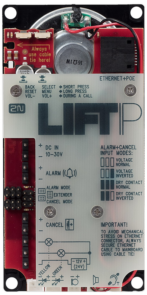
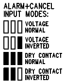
ALARM terminal | Voltage control | 5–48 V DC connection | Use jumpers for configuration. The jumper link is below the ALARM terminal. Voltage connection control: no jumper mounted. Voltage disconnection control: right jumper mounted. N/O contact: all jumpers mounted. N/C contact: left and middle jumpers mounted. |
| |
| Voltage control (inverted) | 5–48 V DC disconnection | ||||
Contact control (N/O) | N/O contact | ||||
| Contact control (N/C) | N/C contact | ||||
CANCEL terminal | Voltage control | 5–48 V DC connection | Use jumpers for configuration. The jumper link is above the CANCEL terminal. Voltage connection control: no jumper mounted. Voltage disconnection control: right jumper mounted. N/O contact: all jumpers mounted. N/C contact: left and middle jumpers mounted. |
| |
Voltage control (inverted) | 5–48 V DC disconnection | ||||
Contact control (N/O) | N/O contact | ||||
Contact control (N/C) | N/C contact | ||||
Extender (6-pin connector) | Used for Voice Alarm Station connection. | ||||
| Indicator connecting terminals | DC 12–24 V / 2× 200 mA externally supplied indicators; keep the wiring diagram. | ||||
“Establishing connection” LED connector | Yellow | The LEDs are not included in the standard delivery (excluding the cable version). | |||
“Connection established” LED connector | Green | ||||
External microphone connector | When an external electret microphone (supplied upon request) is connected, the in-built microphone will be disconnected automatically. | ||||
Speaker connector | The speaker is connected in the standard delivery. | ||||
Induction loop connector (optional) | The induction loop is not part of the standard delivery. Install the induction loop behind a non-conductive and non-magnetic cover. Polarity does not matter.
| ||||
| Button | BACK, RESET, VOL - | Short press (BACK) – quit the system voice menu Long press (RESET) – reset the device in approx. 10 s During a call (VOL -) – decrease the speaker volume | |||
| Button | SELECT, MENU, VOL + | Short press (SELECT) – confirm a selection in the system voice menu (Enter) Long press (MENU) – enter the system voice menu During a call (VOL +) – increase the speaker volume | |||

Warning
- Keep polarity for voltage-controlled ALARM and CANCEL buttons (see the instructions on the cover).
Caution
- You are recommended to turn down the speaker volume to minimise the microphone-speaker feedback (echo).
LED Functions (Back)
| State | Red | Yellow | |
|---|---|---|---|
| System at relax | x | x | |
| Call in progress | x | illuminated | |
| Audio test / System menu | x | flashing | |
| Error (to be solved) | flashing | x | |
| Error (not to be solved by user) | illuminated | x | |
| Enter system menu (voice menu missing) | flashing 3 times | x | |
| State (start or upgrade) | |||
| Upgrade package check | x | flashing | |
| Bootloader | illuminated | illuminated | |
| Upgrade bootloader | illuminated | flashing | |
| Upgrade in progress | flashing | flashing | alternately |
| State | Blue |
|---|---|
| ALARM activation | illuminated |
| CANCEL activation | illuminated |
Note
- The LEDs are on the LiftIP audio unit back side.
LED Functions (Front – during call)
| Colour | Function |
|---|---|
| Yellow | Establishing connection |
| Green | Connection established |
Note
- The LEDs are on the LiftIP audio unit front side.
- External LEDs can be connected too (Establishing connection, Connection established).