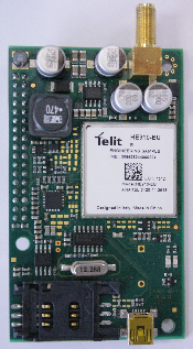
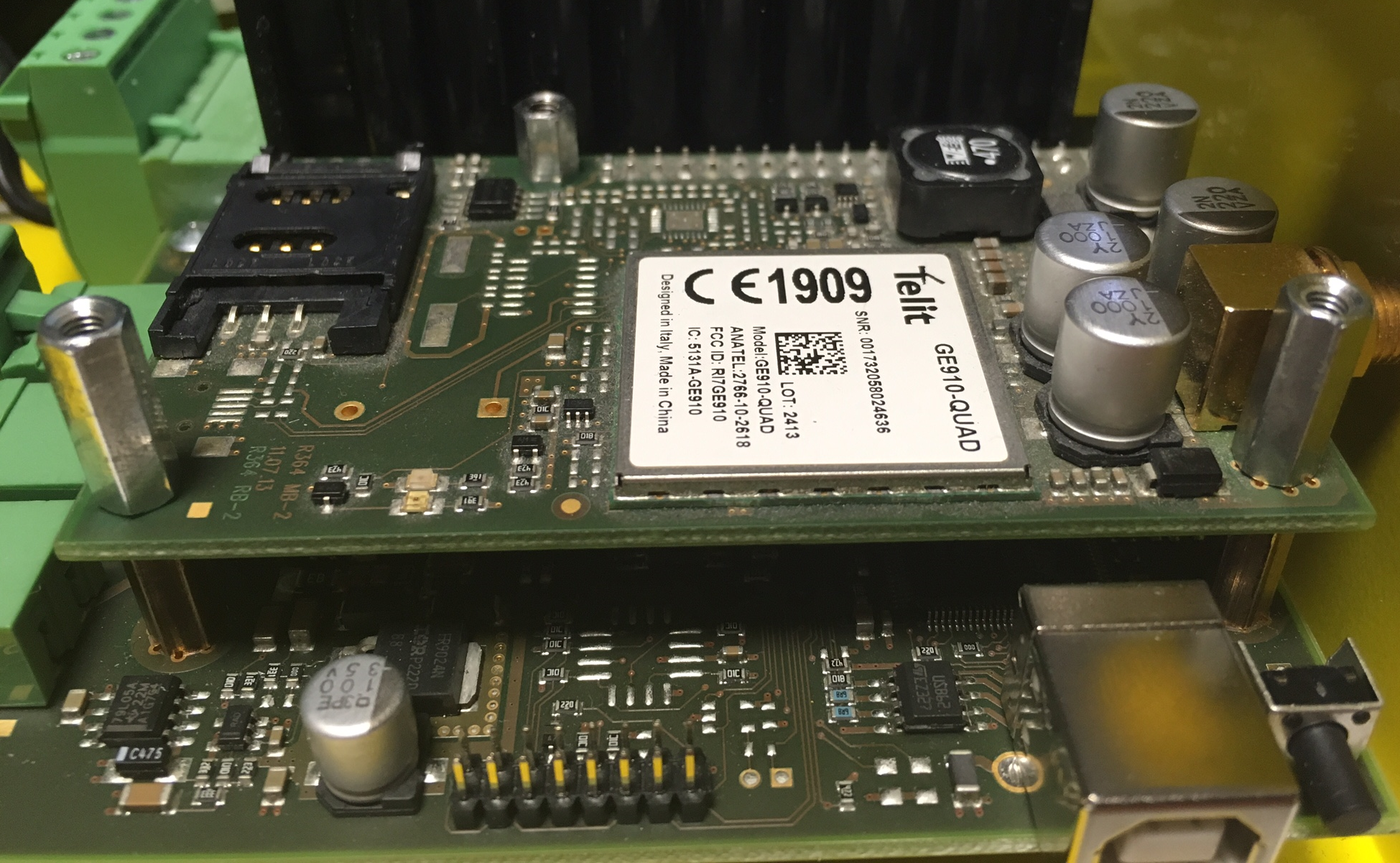
2.8 GSM/UMTS Module
Description of Connection
The module should be part of the Central Unit (hereinafter referred to as CU). If the CU does not contain the GSM/UMTS module, proceed as follows:
- Disconnect the CU from the mains supply.
- Loosen the three screws on the CU upper cover.
- Move the CU upper cover in such a way that you can remove it.
- Proceed with caution while removing the cover: be careful about the drain wire connecting the cover with the CU bottom part. Do not disconnect the wire unless there is a reason to do so!
- Disconnect the back-up rechargeable batteries if available using the battery – CU connecting cable FASTON terminals.
Remove the sealing ring from the CU cover.
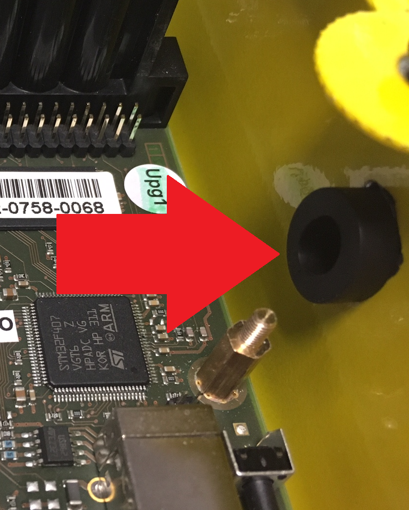
Be careful while mounting the module: push the antenna connector through the CU cover.
Mount the module onto the externally threaded spacers (2) and connect it to the motherboard connector (1).
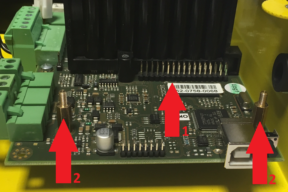
Be careful while putting the module on the pins. Make sure that you have connected all the pins to the module connector.
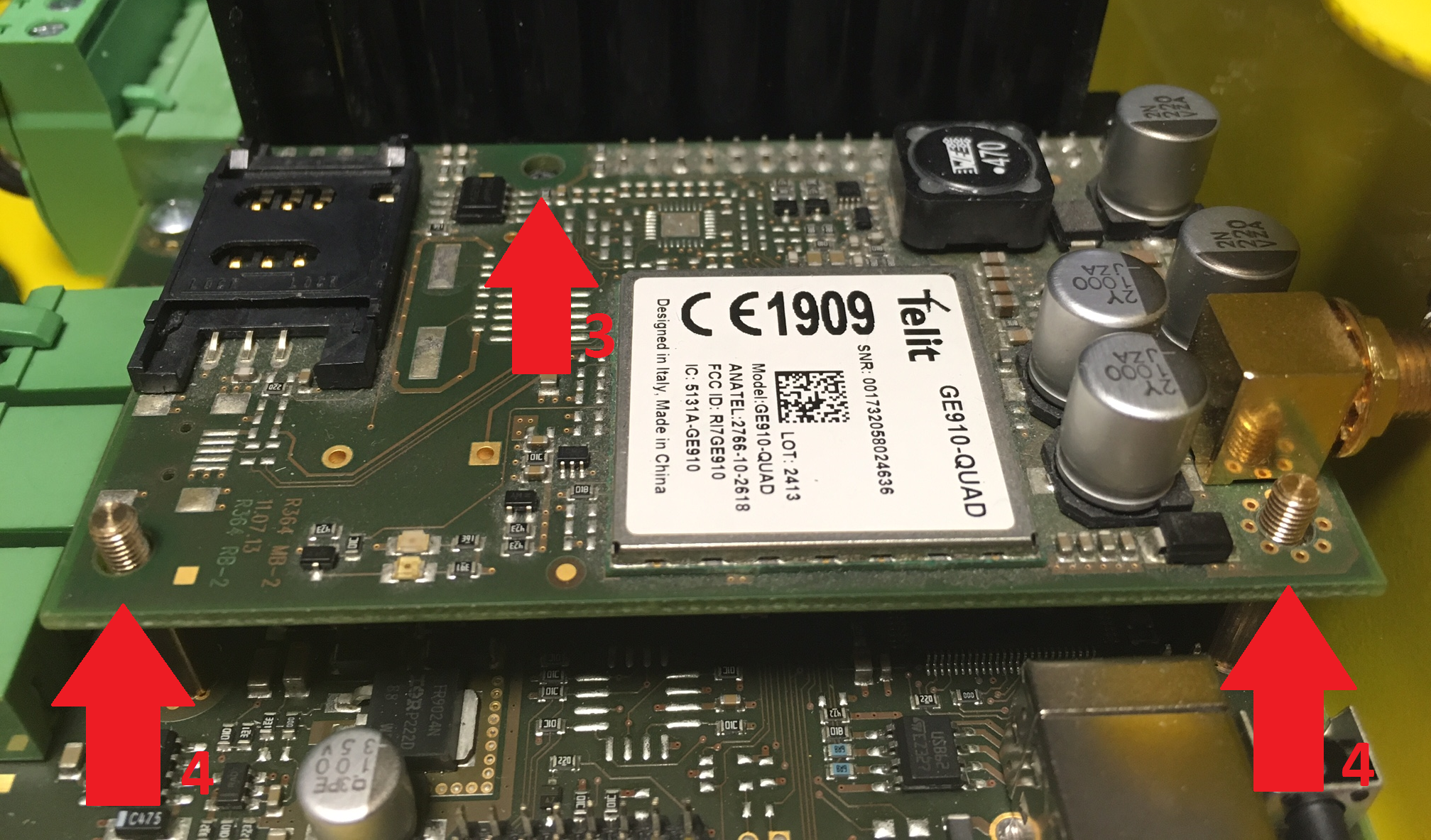
If you have mounted the connector pins correctly, use 1 bolt spacer (3) and 2 threaded spacers (4) to fit the module. Use a 5mm hex socket wrench to fit the spacers.
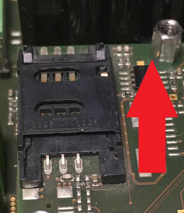
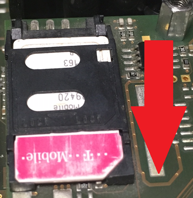
- Now insert the SIM card and connect the antenna.
- Slide and release the SIM card holder (Fig. 1).
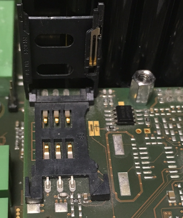
- Tilt out the SIM card holder (Fig. 2).
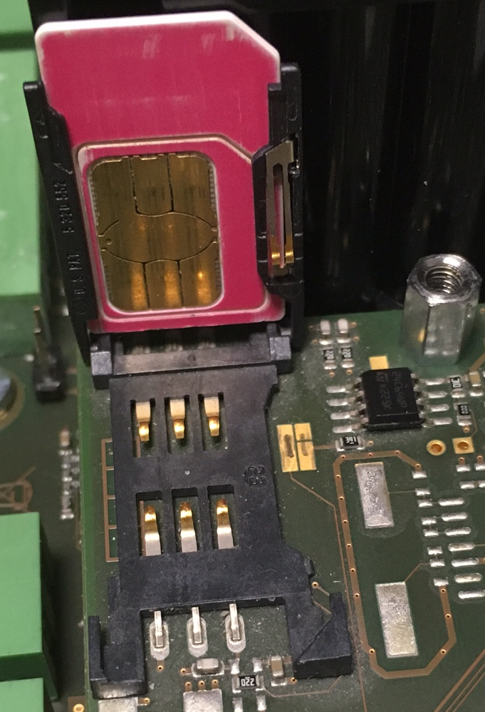
- Insert the SIM card (Fig. 3).
Replace the SIM card holder and lock it into position (Fig. 4).
- Connect the antenna.
- Connect the rechargeable batteries. Reconnect the cover – CU bottom connecting drain wire if disconnected. Replace the cover and tighten the 3 screws.
- Connect the CU to the mains supply.
Warning
- While fitting the module, make sure that all the pins are fitted correctly into the connector to avoid module damage.
Caution
- In places with a poor signal quality find an appropriate place or use a special (directional) antenna.
- Should you have DTMF transmission problems, set parameter 710 to 1 (for GSM modules only).
Signal Strength Levels
| LED colour | red | red – yellow | yellow | yellow – green | green |
| Signal level | > -96dBm | -96dBm <-> -90dBm | -90dBm <-> -74dBm | -74dBm <-> -69dBm | < -69dBm |
Caution
- From version 2.6.0 it is possible to select the preferred network (2G / 3G) for the UMTS module using parameter 711.