2.6 Audio Unit - Compact
Description
Robust, heavy-duty design. Standard-sized ALARM button including signage for the blind and backlit pictograms (hardened glass). Designed for cabin wall mounting. No drilling is required as the device is to be wall-mounted.
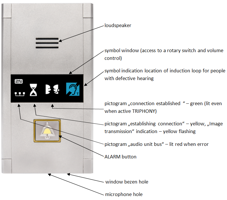 |
Figure: Description of Audio Unit – Cabin Compact
Operation
- Push the ALARM button to activate the audio unit. The 'Establishing connection' symbol goes on. The 'Connection established' symbol goes on when communication is set up.
Before You Start
Requirements
- Make sure that the lift wall is even.
- Make sure that the installation meets the standard requirements (ALARM button height and distance from the other lift buttons, e.g.).
Product Completeness Check
Check the product for completeness before installation.
- 1 Compact audio unit including: one long, 2 mm ballpoint hexagon key wrench4 M4×8 screws
- symbol window
- 3 terminals slid on the backside connector
- 4 M4 x 30 worm screws
- 4 M4 nuts
- 4 fan washers
Mounting
Just drill holes into the cabin wall as shown in the figure below (also see the 1:1 figure on the product box). The larger hole is intended for cabling. Round the hole edges to avoid cable damage!
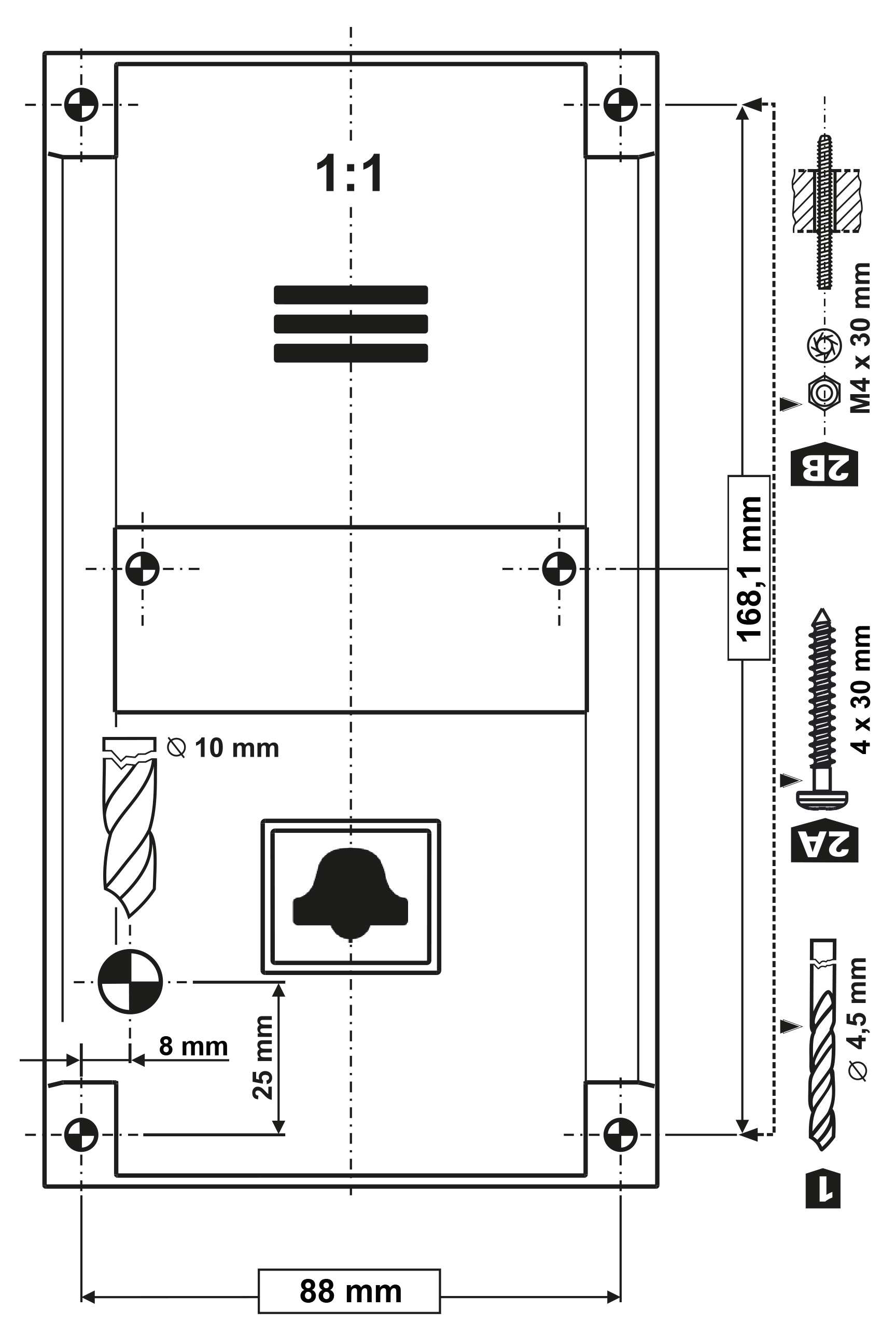 |
Figure: Mounting Hole Dimensions for Audio Unit – Cabin Compact
Note
Two 2.5 mm holes in the symbol window are intended for installations without access to the back side of the installation panel. The 2.5 diameter is suitable for plywood wall mounting (chipboard, laminated plastic, etc.) with the screws included in the delivery. Drill M4-threaded holes for metal panel mounting from the front side.
Do not complete the mounting procedure until connecting the device electrically (see below).
Electrical Installation
Caution
- Connect the wires before mounting the audio unit on the lift cabin wall. The connectors are separable – remove them, connect the wires, tighten the screws and replace the connectors.
Description of Terminals
Terminals | Description | ||
|---|---|---|---|
| AUDIO UNIT BUS | Audio unit bus (2-wire) connection, polarity must be maintained. | ||
ALARM terminals
| Voltage = voltage control (on/off) | 6–24 V DC, any polarity *) | Alarm call activation |
Contact = contact control (on/off) | NO/NC contact *) | ||
CANCEL terminals
| Voltage = voltage control (on/off) | 6–24 V DC, any polarity **) | Alarm call deactivation by door opening |
Contact = contact control (on/off) | NO/NC contact **) | ||
| ALARM 2 terminal | Contact = contact control (closing) | NO contact | Alarm call activation from Alarm set 2 |
*) By default, ALARM is activated by voltage connection or contact closing. Use a rotary switch to apply voltage disconnection and contact opening.
**) By default, ALARM is deactivated by voltage connection or contact closing. Use a rotary switch to apply voltage disconnection and contact opening.
Caution button ALARM 2
- The ALARM 2 button has the N/O contact only.
- Delayed call (914) and Minimum ALARM 1 pressing time (962) do not relate to the ALARM 2 button.
- A short button press (100 ms) sets up a call to the other set of numbers (021–026). If the other set is empty, the call is set up to the first set of numbers (011–016).
- A long button press (3,000 ms) cancels the rescue process if parameter 966 is set.
Bus Connection
Pull the AUDIO UNIT BUS connector out of the terminal board. Connect the audio unit bus (keep polarity as shown on the audio unit cover) and replace the connector.
Warning
- The audio unit is intended for 2N® Lift8 audio unit bus connection exclusively. Do not connect it to other wires to avoid its damage or destruction.
Connectors
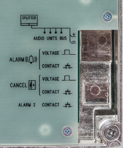 |
Figure: Connectors on Audio Unit – Cabin Compact (New Type)
Safety
- Make sure that the minimum button isolation distance is 1.5 mm and breakdown voltage is 1,500 V. The button contacts may not be connected to any other circuits. If you cannot meet these conditions, use voltage control.
- You can use the switch on the audio unit front side or closing/opening button connected to the ALARM CONTACT connector or both of them if necessary.
Note
- The ALARM button on the cover keeps functional even if an external button is connected.
Rotary Switch
There is a glass-covered rotary switch on the audio unit front side. Use the switch to set ALARM/CANCEL (normal/inverted input) and audio unit type (cabin, cabin roof, cabin bottom, shaft bottom).
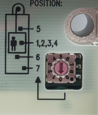 |
| Procedure | Rotary switch position |
|---|---|
1. Insert the hexagonal spanner (included) in the hole on the product bottom edge (window lock screw) and turn left (about 10 times) until you feel resistance. | Position 1 – ALARM normal, CANCEL normal, cabin |
2. The window slides down by itself or with a slight aid, revealing its upper brim. | Position 2 – ALARM inverted, CANCEL normal, cabin |
| 3. Tilt the window forward and remove it. | Position 3 – ALARM normal, CANCEL inverted, cabin |
| 4. Set the required address. | Position 4 – ALARM inverted, CANCEL inverted, cabin |
| 5. Replace the window. | Position 5 – cabin roof
|
6. Insert the hexagonal spanner (included) in the hole on the product bottom edge (window lock screw) and turn right (about 10 times) until the window slides under the panel edge. Tighten slightly. | Position 6 – cabin bottom |
| Position 7 – shaft bottom | |
| Positions 8, 9, 0 / not used (red bus LED flashing) |
ALARM and CANCEL Setting (Rotary Switch)
Contact closing/voltage connection control of ALARM and CANCEL
- Set the rotary switch (under the front glass) to position 1 to make ALARM/CANCEL be controlled by contact closing or voltage connection.
Contact opening/voltage disconnection control of ALARM, contact closing/voltage connection control of CANCEL
- Set the rotary switch (under the front glass) to position 2 to make ALARM be controlled by contact opening or voltage disconnection and CANCEL be controlled by contact closing or voltage connection.
Contact closing/voltage connection control of ALARM, contact opening/voltage disconnection control of CANCEL
- Set the rotary switch (under the front glass) to position 3 to make ALARM be controlled by contact closing or voltage connection and CANCEL be controlled by contact opening or voltage disconnection.
Contact opening/voltage disconnection control of ALARM and CANCEL
- Set the rotary switch (under the front glass) to position 4 to make ALARM and CANCEL be controlled by contact opening or voltage disconnection.
Caution
- Use 6 to 24 V DC of any polarity. However, make sure that the power supply is backed up against power outage.
- Combine the control with buttons if you need to activate ALARM and CANCEL from more sites.
CANCEL input connection (door contact, optional)
This input helps you cancel the rescue request if the lift is fully functional. Press ALARM to make the system wait for a defined period of time, which slightly longer than the maximum lift ride. If functional, the lift reaches the required station and opens the door within the timeout, thus cancelling the rescue request. If the lift door does not open, the rescue request is accepted.
Make sure before installation that the door opening signal is available in the lift cabin.
Requirements
- If the lift is equipped with a double door, the signal must be active only if both the door parts are open and the people can leave the cabin safely.
- The door opening signal must be active even during power outage.
Note
- Make sure that delayed calling is configured to make the CANCEL input connection effective.
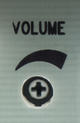
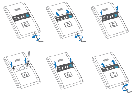
Volume Setting
- Insert the hexagon key wrench (included in the delivery) in the hole on the product bottom edge (window lock screw) and turn left (about 10 times) until you feel resistance.
- The window slides down by itself or with a slight aid, revealing its upper brim.
- Tilt the window forward and remove it.
- Set the required volume level using a trimmer.
- Replace the window.
Insert the hexagon key wrench (included) in the hole on the product bottom edge (window lock screw) and turn right (about 10 times) until the window slides under the panel edge. Tighten slightly.
Caution
- Use the trimmer to set the best acoustic properties eliminating feedback.
Mounting Completion
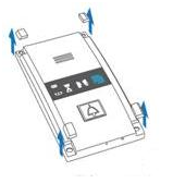
Having connected the wires, you can complete the 2N® Lift8 wall mounting. If you can access the cabin wall from the outside, use the mounting type that prevents dismantling and unauthorised tampering from the cabin. Mounting procedure:
- Where access from the outside is possible, use the four pre-drilled M4 holes in the corners.
- Remove the corner covers fitted with four M4 screws from behind.
- Screw the 30 mm long M4 headless grub screws included in the audio unit package in place of the corner cover screws removed. Tighten the screws with an internal hexagon key wrench.
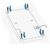
- Put the audio unit on the holes, apply the serrated lock washers from the outside and screw the M4 nuts (both included in the delivery).
- This type of mounting is suitable for lift cabin wall thickness of up to 20 mm.
  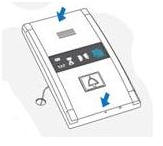 |
If you cannot access the cabin wall from the outside, use the screws under the pictogram glass:
- Insert the hex key wrench (included in the package) in the hole on the product bottom edge and turn it left (about 10 times) until it puts up resistance.
- The window slides down by itself or with little assistance, showing its upper brim.
- Tilt the window forwards and remove it.
- Now you have access to two holes in the window corners. Put 2N® Lift8 on the pre-drilled lift cabin wall holes and fit it with the included screws, which are suitable for plywood, chipboard, laminated plastic etc. walls. For other materials, use appropriate screws or M4 screws in the pre-drilled M4 threaded holes.
- Replace the window and insert the hex key wrench in the bottom edge hole turning it right about 10 times until the window slides under the panel edge. Tighten the window applying a moderate force.
 |
Connection of induction loop for hearing-impaired persons
The induction loop for people with impaired hearing is part of the Compact cabin audio unit. No more accessories are required for the given case.