2.3 Audio Unit - COP
Description
The user does not come into a direct contact with this product. The control and indication elements depend on the specific installation. The functions of the indication elements correspond to the applicable standards
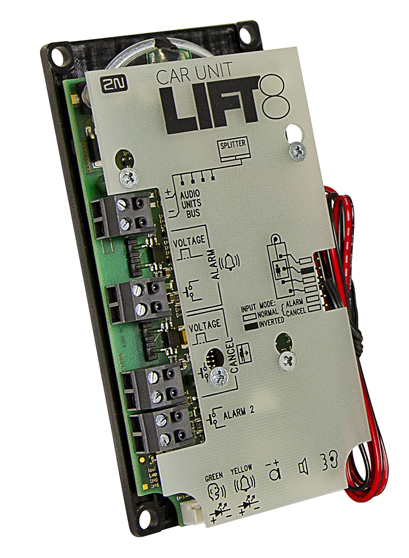 |
Figure: Audio Unit – COP
Caution – diodes
Alarm call
- The yellow LED is illuminated to indicate the call setup progress (request received).
- The green LED is on to indicate call confirmation (connection confirmed).
- The yellow LED starts flashing when the call has been confirmed to indicate camera image downloading.
Upgrade
- The yellow and green LEDs are on (request received and connection confirmed) and the red LED is illuminated on the back side to indicate audio unit initialisation.
- The yellow and green LEDs flash to indicate audio unit upgrading. The red LED on the back side is permanently on.
- No LED is illuminated upon upgrade and the audio unit is ready for use.
Before You Start
Installation Conditions
- The panel has to be installation-ready, including speaker perforation.
- The panel has to be equipped with the following obligatory elements:
- ALARM button;
- illuminated pictogram “Request received”;
- illuminated pictogram “Connection made”.
- The above mentioned elements have been located as required by the applicable regulations.
- There must be free space of at least 65 x 130 x 20 mm behind the panel.
Product Completeness Check
Check the product for completeness before installation.
The cabin audio unit package contains (assembled):
- 1 electronics board
- 4 terminals slid onto the board; see the photo
- 1 jumper slid onto the board; see the cover printing
- 1 mounting panel
- 1 speaker connected directly or by cable
- 1 microphone connected directly or by cable
- 1 cover with printing
- 5 tightening straps
Mounting
Electronics Mounting
This audio unit is intended for mounting behind the lift control panel. Typically, the panel is ready for installation as shown in the drawing below:
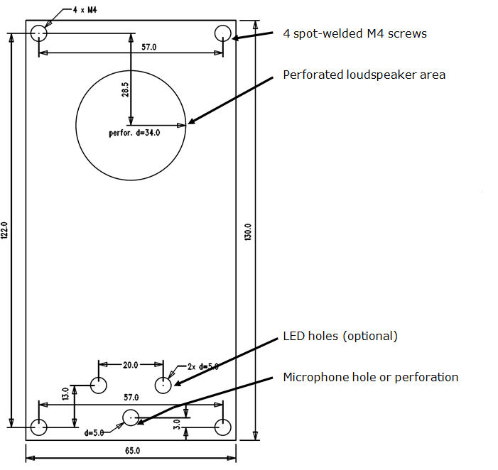 |
Figure: Mounting Hole Dimensions for Audio Unit – COP
To mount the audio unit, you need 4 electrically spot welded M3 or M4 screws, a sufficiently perforated speaker area and a microphone hole. In emergency, you can fix the audio unit on a perfectly degreased surface with a high-quality double-sided foam self-adhesive tape.
Safety
- Leave no gap between the lift control panel and the audio unit surface to avoid acoustic speaker fault and acoustic speaker-microphone feedback.
- Do not use this type of audio unit in a position other than mounted on a sufficiently large board. The acoustic properties of an uninstalled audio unit cannot be guaranteed.
Separate Microphone Mounting
If the microphone is supplied separately with a cable on a 25 x 25 mm large board with self-adhesive foil, just glue it directly behind any hole in the panel (one hole must have the minimum diameter of 5 mm, a group of smaller holes must have the same total area). Be sure to degrease and clean the surface carefully before!
Requirements
- The minimum distance between the loudspeaker and microphone centres is 90 mm. A lower distance may lead to acoustic feedback. A greater distance (within the available 1m cable) does not matter.
- The microphone must be stuck on so that it does not pick up (even in part!) the acoustic pressure from the space behind the control panel. Such sensing might result in acoustic feedback since the speaker strongly radiates sound into the cavity.
Separate Speaker Mounting
The speaker is equipped with a cable and can be separated from the electronics (simply pulled out) within the reach of the cables delivered (1m). This option is useful where there is not enough space for the whole electronic equipment. Fit the speaker according to the instructions below:
- While gluing the speaker choose such procedures or adhesives that prevent membrane damage by adhesives and volatile substances or heat.
- We recommend you to keep the speaker sealed to eliminate vibrations and provide electrical insulation.
Frequently Asked Questions about Speaker
- Is it possible to use a common speaker for the communicator and floor announcer?
No, it is not possible.
- May I use a speaker of my own?
Yes, but make sure that the impedance is 64 Ω. By doing this you assume responsibility for sufficient volume and frequency range.
- May I place the speaker on the cabin ceiling?
This placement is not recommended.
- May I use a longer cable to the speaker?
For the speaker yes, but we do not recommend it for the microphone.
Electrical Installation
Description of Terminals, Connectors and Jumpers
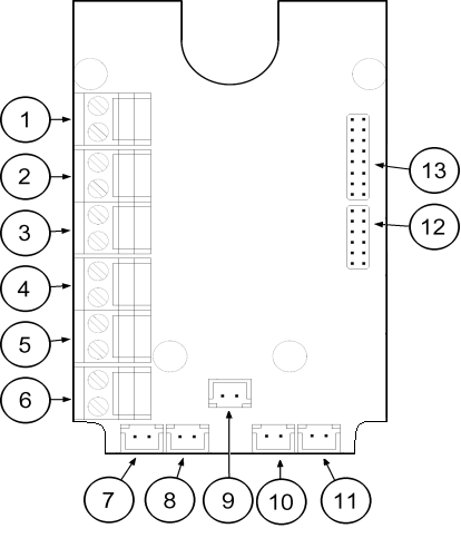 |
Figure: Terminals, Connectors and Jumpers on Audio Unit – COP
Terminals | Connectors | ||
|---|---|---|---|
1 | Audio unit bus | 7 | “Connection made” LED |
2 | ALARM, voltage activation | 8 | “Request received” LED |
3 | ALARM, contact activation | 9 | Microphone connector (optionally) |
4 | CANCEL, voltage activation | 10 | Induction loop connector |
5 | CANCEL, contact activation | 11 | Speaker connector |
6 | Alarm 2 (set 2) | 13 | Servicing connector |
Configuration jumpers | Two LED signal lamps (other side) | ||
12 | Audio unit position | 1. (yellow) | Request received |
12 | ALARM and CANCEL negation | 2. (green) | Connection confirmed |
Note
- If external LEDs are connected to connectors 7 and 8, LED indicators 1 and 2 will not be shining.
Audio Unit Location Configuration
The audio unit is configured as a cabin audio unit by default and so it is not necessary to change the configuration. To use the audio unit in a room other than the lift cabin, proceed as follows.
Procedure
- Reconfigure the jumper on configuration jumper 12.
- If there is poor access to the pins, you can remove the electronics cover. Slightly loosen the four screws and shift the cover downwards. Now you can remove the cover.
- The first 4 pins help set the audio unit location (1 – cabin ceiling, 2 – cabin, default, 3 – under cabin, 4 – shaft bottom, 1+ 4 – cabin 2 roof, 2+ 4 – cabin 2, 3 + 4 under cabin 2). Use the jumpers for 1–4 settings. In cabin 2 setting, set one jumper to the shaft bottom position (4) and then select the position with the other jumper (1 – cabin 2 roof , 2 – cabin 2, 3 – under cabin 2).
- Configure the required changes as printed on the electronics cover.
- If you have removed the cover, put it back in the original position and tighten the screw.
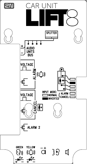 |
Figure: Address Configuration for Audio Unit – COP
Caution
- In versions 2.0.0 and higher, up to 7 audio unit positions can be configured for two-cabin lifts (1 – cabin roof, 2 – cabin = default, 3 – under cabin, 4 – shaft bottom, 5 – cabin 2 roof, 6 – cabin 2, 7 – under cabin 2).
- Up to 5 audio units including the Fireman unit and module camera can be connected to one shaft.
Note
- Make sure that no two audio units have an identical address to avoid system error.
- The position-setting jumpers are employed exceptionally, e.g. where a certain audio unit type is used in a position other than normally intended.
- To recover the initial address setting, follow the drawing on the cover.
Bus Connection
Pull the terminal out of connector 1 – Audio units bus, connect the bus audio units wires and replace the terminal to connector 1. Mind the polarity.
Warning
- The audio unit is intended for 2N® Lift8 audio unit bus connection exclusively. Do not connect it to other wires to avoid its damage or destruction.
- Maintain polarity while connecting the audio unit to avoid audio unit error.
Caution
- The audio unit is powered via a 2-wire bus. Disconnection of these wires results in the audio unit switch-off.
- Avoid the audio unit address duplicity.
ALARM Button Connection
Requirements
- The ALARM button design (colour, symbol, keypad surface, mechanical operation) and location have to meet the requirements of the particular installation.
Button control
Requirements
- The ALARM button has to be equipped with a make or break (NO/NC) contact that is not connected with any other circuit.
- None of the ALARM button terminals may be connected electrically with any other electrical circuit and no voltage source other than the NO/NC contact may be connected to them.
- If one of the ALARM contacts is connected to another circuit, an appropriate isolation strength according to the applicable standards has to be ensured between the contacts.
Procedure
- Leave the ALARM terminal in the lower position (3).
- If you use a make contact, leave the jumper as it is (5th pin on jumper 12) – ALARM without jumper fitted (factory setting).
- If you use a break contact, fit the jumper (5th pin on jumper 12) – ALARM inverted – jumper fitted.
Voltage control
Requirements
- DC 12 to 48 V voltage
- The voltage signal must be active even during a power failure.
Procedure
- Move the ALARM terminal two pins up into position (2).
- For activation by voltage connection, leave the jumper as it is (5th pin on jumper 12) – ALARM without jumper fitted (factory setting).
- For activation by voltage disconnection, fit the jumper (5th pin on jumper 12) – ALARM inverted – jumper fitted.
Warning
- Ignoring the instructions above may lead to product damage.
Caution button ALARM 2
- The ALARM 2 button has the N/O contact only.
- Delayed call (914) and Minimum ALARM 1 pressing time (962) do not relate to the ALARM 2 button.
- A short button press (100 ms) sets up a call to the other set of numbers (021–026). If the other set is empty, the call is set up to the first set of numbers (011–016).
- A long button press (3,000 ms) cancels the rescue process if parameter 966 is set.
CANCEL Input Connection (Door Contact, Optional)
This input helps cancel a rescue request if the lift is fully functional. When the ALARM button is pressed, the system waits for a pre-programmed period of time, which is a little longer than the maximum lift running time. If the lift is functional, it arrives in the required station within this timeout and opens the door. In that case, the rescue request is cancelled. If the door does not open, the request is accepted.
Find out before installation whether the door opening signal is available in the lift cabin.
Requirements
- If the lift has a double door, the signal must be active only if both the door sets are open, i.e., if it is really possible to leave the cabin.
- The door position signal has to work even in the case of power outage.
Contact control
Requirements
- None of the contact outlets terminals may be connected electrically with any other electrical circuit and no voltage source other than the NO/NC contact may be connected to the CANCEL terminals.
Procedure
- Leave the CANCEL terminal in the lower position (5).
- f you use a make contact, leave the jumper as it is (6th pin on jumper 12) – CANCEL without jumper fitted (factory setting).
- If you use a break contact, fit the jumper (6th pin on jumper 12) – CANCEL inverted – jumper fitted.
Voltage control
Requirements
- DC 12 to 48V voltage
Procedure
- Move the CANCEL terminal two pins up into position (4).
- For activation by voltage connection, leave the jumper as it is (6th pin on jumper 12) – CANCEL without jumper fitted (factory setting).
- For activation by voltage disconnection, fit the jumper (6th pin on jumper 12) – CANCEL inverted – jumper fitted.
Warning
- Ignoring the instructions above may lead to product damage.
- The CANCEL function only works when the cabin audio unit is set to the cabin position (default).
Caution
- Remember to program delayed calling to make the CANCEL connection work successfully.
- Refer to the electronics cover for the ALARM and CANCEL configuration scheme.
LED Indicator Connection
The current LED technology makes it possible to achieve a relatively good light intensity with a small current. If the lift indicators are illuminated with a sufficiently efficient LED requiring a current of approx. 5 mA (with diode loss of about 2 V), no power supply is needed. See the figure below for the connection.
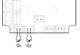 |
Figure: Alternative LED Connection for Audio Unit – COP
Note
- The cables required for this configuration are not part of the standard delivery but are available upon agreement.
- In this configuration, the auxiliary indicators on the PCB are not illuminated.
External Pictogram Driver
 |
Description
The device transforms the 2N® Lift8 Car Unit LED outputs into a universal pilot lamp, whose outputs are capable of driving two lamps rated at the maximum of 36 Volts, 0.5 Amps. The outputs are galvanically isolated from the Car Unit. Since the lamp outputs are polarity independent, both AC and DC power supplies can be used for powering the lamps. To protect the Car Unit and Pictogram Driver against damage caused by shorts, always use the included isolating tube when installing the device!
Wiring diagram
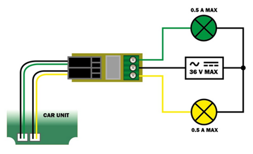 |
Caution
External pictograms are connected to connectors 7 and 8 on the cabin audio unit.
The manufacturer, 2N TELEKOMUNIKACE a.s., hereby declares that the 2N® Lift8 External Pictogram Driver is in compliance with the essential requirements and other relevant provisions of the 1999/5/EC Directive. The Declaration of Conformity is attached to the basic module of 2N® Lift8 and also available at www.2n.cz.
Volume Configuration
Slightly loosen the four screws and shift the cover downwards. Now you can remove the cover. Use the trimmer located in the bottom part of the electronics to set the required volume level (see the figure below).
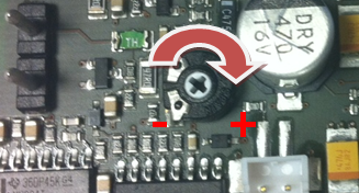 |
Caution
- Use the trimmer to set the best acoustic properties eliminating feedback.
Induction Loop Connection
The regulations that apply to communicator installations may require a mandatory loop for persons with defective hearing in the lift cabin. In that case, connect the loop to connector (10) with any polarity. The loop including a 1m long cable can be part of your delivery if agreed so.
Requirements
- The induction loop has to be placed behind a non-metal, non-magnetic cover in the control panel as the magnetic field of the induction loop cannot go through a metal control panel.
- The induction loop has to be labelled with an appropriate symbol (ear) placed according to the applicable standards.
Rescue Process
- The rescue (extrication) process is activated after the alarm call end.
- The yellow LED keeps shining on the audio unit.
- The service technician enters a valid password via the 2N® Lift8 voice menu to terminate the process.
- When the rescue password is entered via the voice menu, the yellow LED goes off on the audio unit and the 'Rescue process was terminated' is played.
Caution
- Access the voice menu (during an incoming call to L8 or from the machine room) to terminate the rescue process. Enter the administration menu (9) and press (2) to terminate the rescue process. Enter the shaft number (only if multiple audio units are involved in the rescue process) and enter the rescue terminating password.
Warning
- Remember to set the rescue password (parameter 992) to activate the rescue function.
- The rescue process can only be activated on a cabin audio unit configured as the cabin (default audio unit setting).