2.2 Splitter
Description
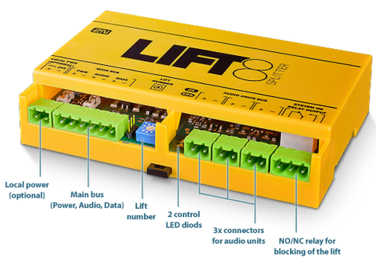
The splitter helps extend installations by interconnecting audio units in multiple lift shafts (audio units can be connected directly to the CU in one-shaft installations). It is connected with the CU via six wires (power, audio, data). Audio units are connected to the splitter using a two-wire bus. The splitter also contains a make/break contact for the lift blocking function. There can be up to 7 splitters (according to the count of lift shafts).
Each splitter must be configured for a different address (lift shaft number) for the system to work. The addresses are 2–8 (lift 2–8). Lift 1 is the CU.
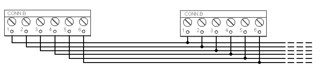
The splitters are connected in series, i.e. one after another (never in parallel), to avoid system instability. The termination resistance (jumper) is mounted on the last splitter or IO module (furthest from the CU).
 |
2N® Lift8 Splitter
Caution – upgrade
- Set the splitters to odd addresses (lift/shaft number) for 1.x.x to 2.x.x upgrade as even addresses cannot be upgraded. Example: First upgrade the odd address splitters. Then disconnect these spliters and change the even address splitters to odd ones. After upgrade, change the odd addresses back to even ones.
- The upgrading process is indicated by green and red flashing LEDs (OK and ERR respectively).
Caution
- Local power supply is not supported yet.
Electrical Installation
Main Bus Connection
Remove the push-in terminal board from the main bus connector and connect six wires from the CU maintaining the polarity (power + −, audio + −, data + −). See the printed figure on the splitter cover.
Main bus |
|---|
1 … Main bus power + |
2 … Main bus power − |
3 … Main bus audio + |
4 … Main bus audio − |
5 … Main bus data + |
6 … Main bus data − |
 |
Warning
- Maintain the connection polarity to avoid a 2N® Lift8 error.
Bus Connection between Audio Units and Splitter
Interconnect the splitter and audio units using a two-wire bus maintaining polarity.
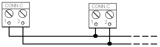 |
Audio unit bus |
|---|
1 … Bus for Audio Units + |
2 … Bus for Audio Units − |
Address Configuration
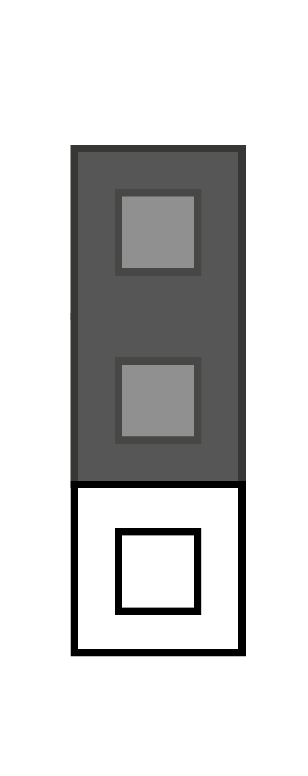
Configure the splitter address for the given lift using a 10-position switch 0–9 (see the figure).
Configure lift 2–8 as 2–8 (set the switch to position 5 for lift 5, e.g.).
Warning
- Do not configure the splitter address as 0, 1 and 9 or the system will report a fault
- Address 1 is used by the central unit
Audio Unit Connection
Connect up to 5 audio units to each splitter. As the splitter has only 3 audio unit terminals, connect 1–2 audio unit in parallel. Remove the slide-on terminals from the audio unit connectors and connect the twin-wire. Adhere to polarity to avoid the audio unit error. Refer to the schemes printed on the splitter and audio unit for connection polarity.
Requirements
- Connect up to 2 audio units to one terminal.
- With multi-strand cables, always use a pair of wires which match each other. In standard UTP cables the paired wires are twisted around each other.
- With special cables (to the cabin), use the neighbouring wires and make sure that the nearest surrounding wires do not radiate interference (power wire, video signal etc.).
Recommendation
- Do not run the bus near power wires, especially long sections.
- Branch the bus to shorten the total length of sections.
Warning
- The bus is electrically isolated from the telephone line circuits according to the EN60950 standard requirements and its low voltage cannot cause any electrical accident.
Lift Blocking Function Connection
Lift blocking is enabled by the contact breaking (opening) when there is a telephone line (PSTN, GSM, UMTS, VoIP) fault or if the 2N® Lift8 rechargeable batteries are almost flat. Connect the contact to the relevant input of the control electronics of the lift/group of lifts. The control electronics must ensure that, after the contact opening, the lifts in operation go down to the nearest station and the doors open.
Caution
- This function may be mandatory depending on the regulations applicable for the given country and time of installation.
Termination Resistance
Caution
- Find the 3-pin termination resistance setting jumper between the main bus connector and the lift number switch.
- Connect the jumper to the first and last devices (CJ, splitter or IO module) connected to the bus in the termination resistance switching position, see the figure below.
- Refer to the CU describing section for more details on termination resistance mounting.
- The device that is not at the first/last bus position must be equipped with a 3-pin jumper in the off position.
- By default, the termination resistance jumper is off.
 |
 |
Termination Resistance ON
 |
Termination Resistance OFF
Termination Resistance ON
Mounting Types
See below for the mounting types and necessary components. Install the device on sites not exposed to water leakage or condensation.
Wall Mounting
Use appropriate wall plugs and screws for mounting (not included in the delivery). Hang the device using the pre-drilled holes on the device bottom.
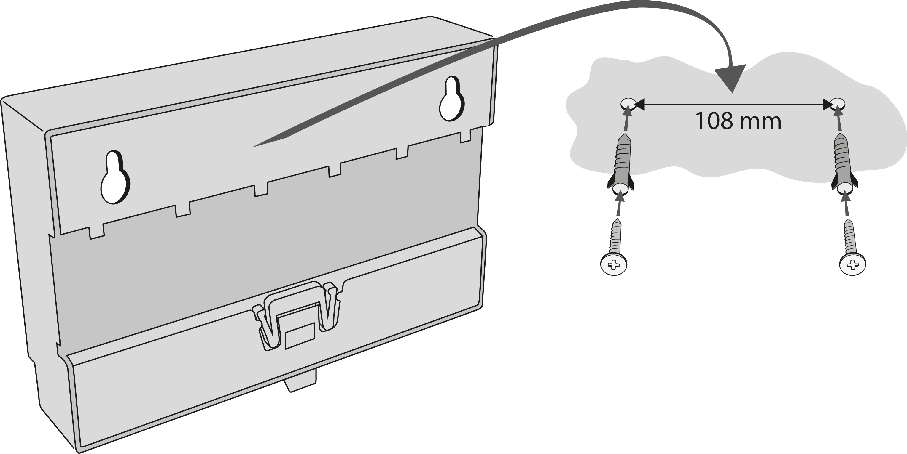 |
Wall Mounting
DIN Rail Mounting
Its possible to mount device on standard DIN rail TS 35. Min. rail length is 14 cm.
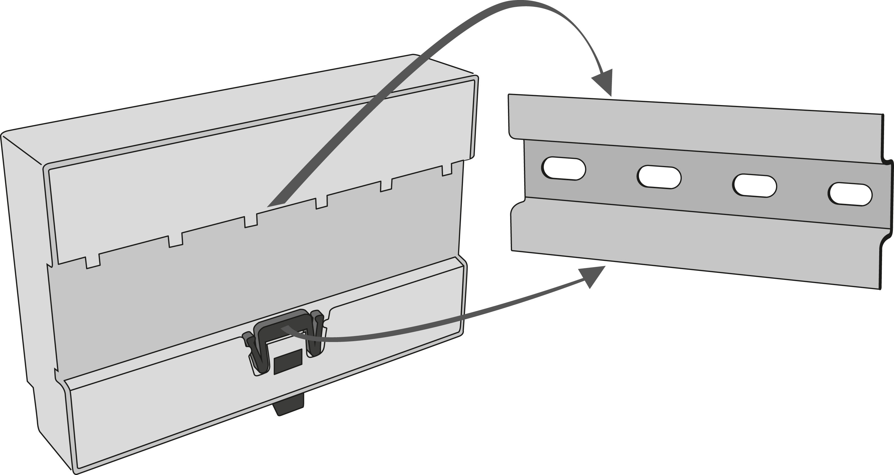 |
DIN Rail Mounting
Caution
- The warranty does not cover any defects or failures of the product arisen as a result of improper mounting in contradiction to these instructions.
- A wrong mounting procedure may lead to damage to the electronics due to water infiltration. The splitter circuits are constantly under voltage and water leakage causes electrochemical reaction. No warranty can be claimed for products damaged in this manner!