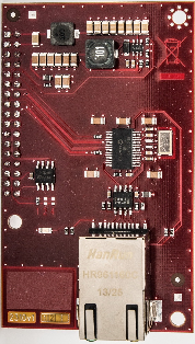
2.10 VoIP Module
Description of Connection
The module should be part of the Central Unit (hereinafter referred to as CU). If the CU does not contain the VoIP module, proceed as follows:
- Disconnect the CU from the mains supply.
- Loosen the three screws on the CU upper cover.
- Move the CU upper cover in such a way that you can remove it.
- Proceed with caution while removing the cover: be careful about the drain wire connecting the cover with the CU bottom part. Do not disconnect the wire unless there is a reason to do so!
- Disconnect the back-up rechargeable batteries if available using the battery – CU cable FASTON terminals.
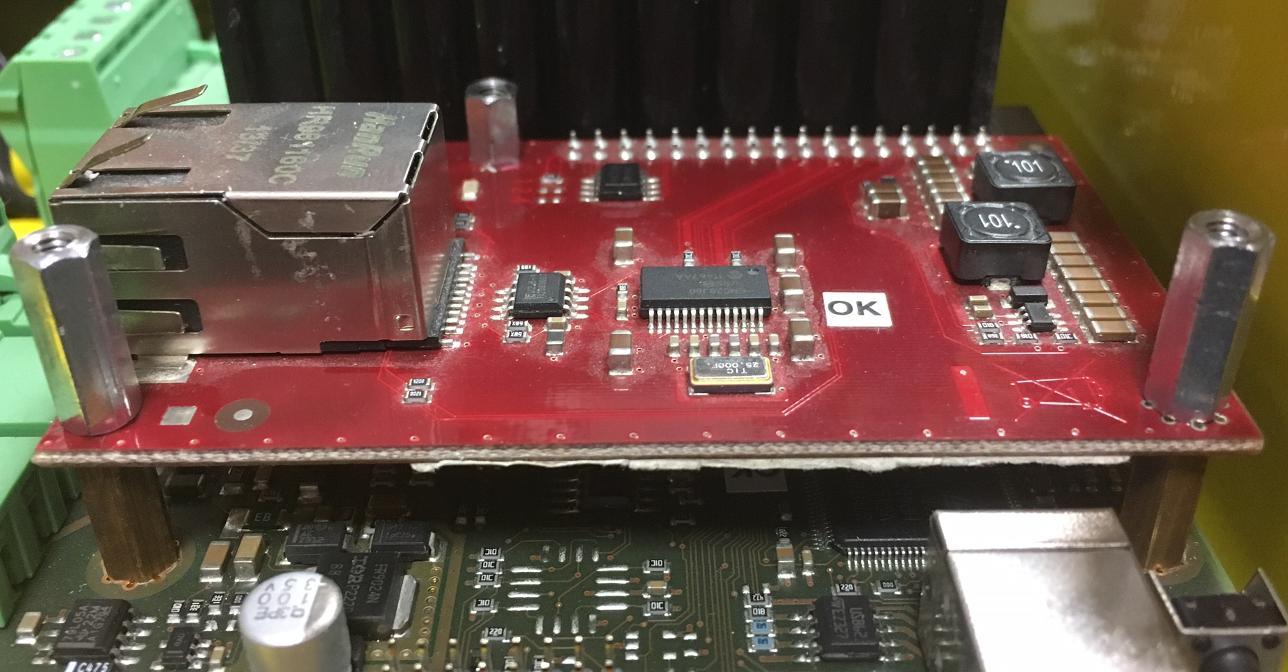
Mount the module onto the externally threaded spacers (2) and connect it to the motherboard connector (1).

- Be careful while putting the module on the pins. Make sure that you have connected all the pins to the module connector.
If you have mounted the connector pins correctly, use 1 bolt spacer (3) and 2 threaded spacers (4) to fit the module. Use a 5mm hex socket wrench to fit the spacers.
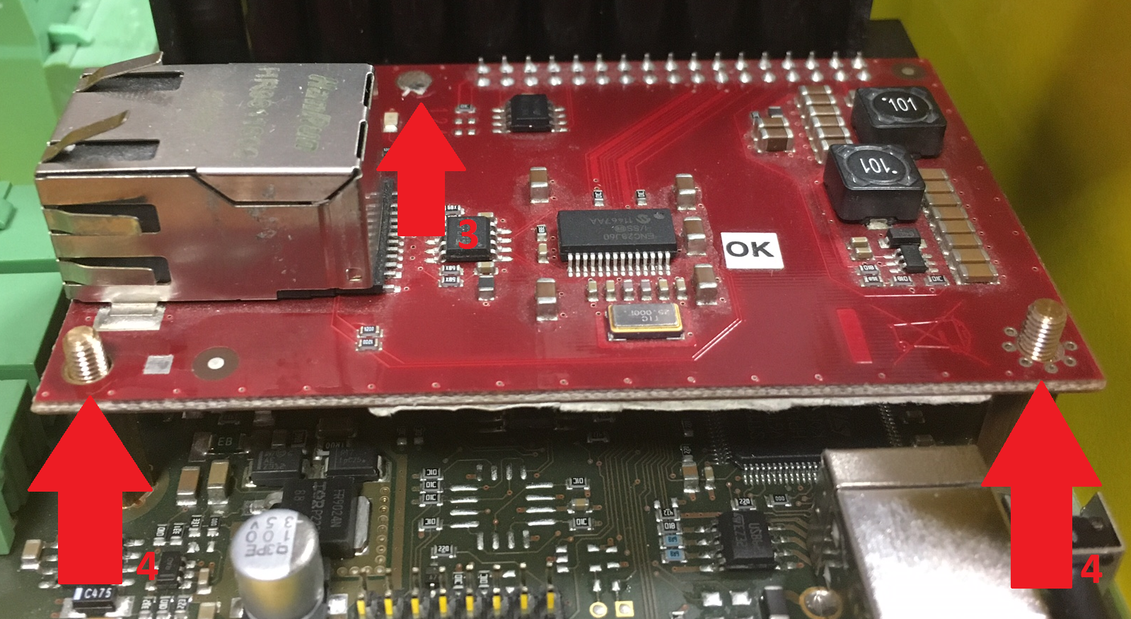
- Now connect the VoIP line via the RJ-45 connector.
- Connect the rechargeable batteries. Reconnect the cover – CU bottom connecting drain wire if disconnected. Replace the cover and tighten the 3 screws.
- Connect the CU to the mains supply.
Warning
- While fitting the module, make sure that all the pins are fitted correctly into the connector to avoid module damage.
Caution
- The A-Law codec is only supported in 2N® Lift8.