2.6 Installation – Compact Version
Caution
- Be sure to connect the wires before wall mounting. The connectors are separable – remove them, connect the wires, tighten the screws and replace the connectors.
Safety Precautions
- The product is connected to a telephone line where life-endangering voltage may occur, during storms in particular. Be sure to install the ALARM button in such a manner that the user cannot get in touch with the wires and can be protected against electrical accident. The minimum isolation distance must be 1.5 mm and/or the minimum breakdown voltage must be 1,500 V – for the used button too!
- Make sure that the cables cannot get in contact with sharp edges during installation to avoid insulation damage.
- Check after installation that the isolation distance of 1.5 mm is kept everywhere. Use an insulation meter if possible.
- The manufacturer shall not be held liable for any installations made in conflict with the User Manual or the Appendix thereto.
Electrical Installation
| Terminals The ALARM terminal block helps activate alarm calls. The ALARM button on the cover of button versions remains active even if an external button is connected or voltage control is used for activation. Press button 2 (ALARM2) to set up a call to the numbers in memory 021–026 to end the rescue mode in case the rescue process is active and parameter 966 is set to 1 or 3. The CANCEL terminal block helps deactivate an active alarm when the door opens. Therefore, set parameter 914 to a value higher than the maximum lift travelling time. | Terminals on the rear side
| |
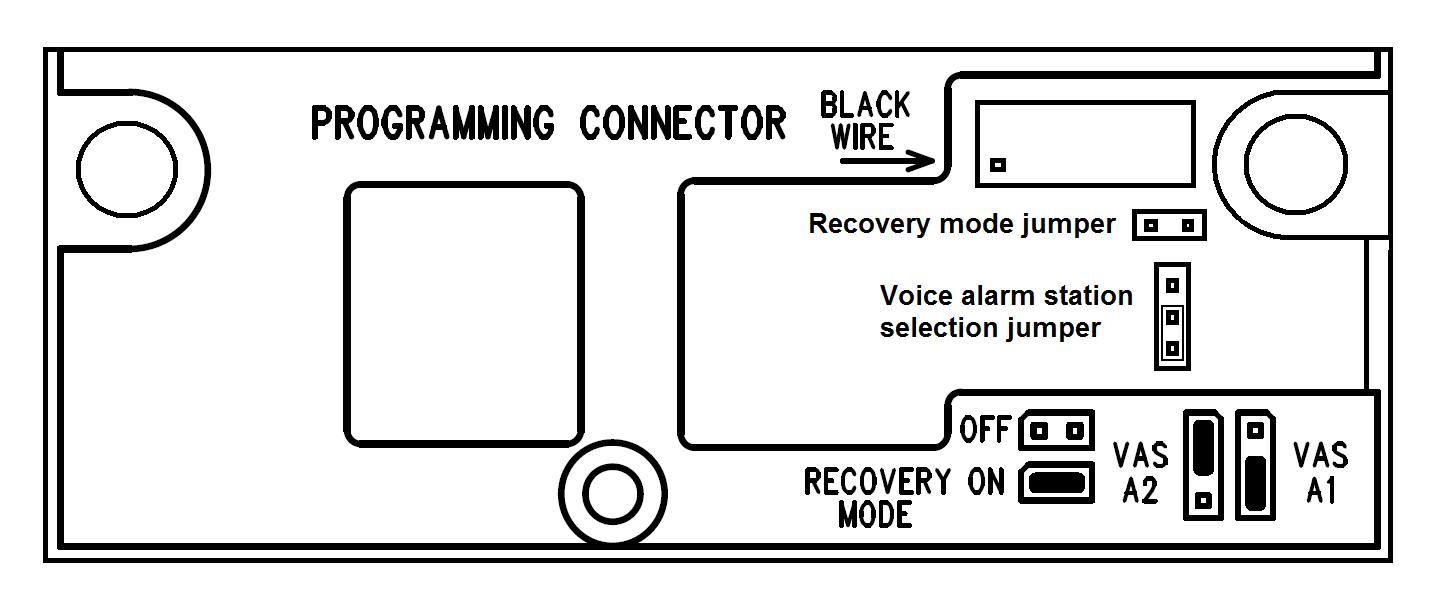
Programming connector – use the 2N® Lift1 programmer to interconnect Lift1 with a PC and program it via the Service Tool. Recovery mode – refer to the Electric Installation table. The Voice Alarm Station selecting jumper defines the set of numbers to dialled by the Voice Alarm Station (011–016 or 021–026). VAS A1 – set 011–016 VAS A2 – set 021–026 | Connectors at front glass
|
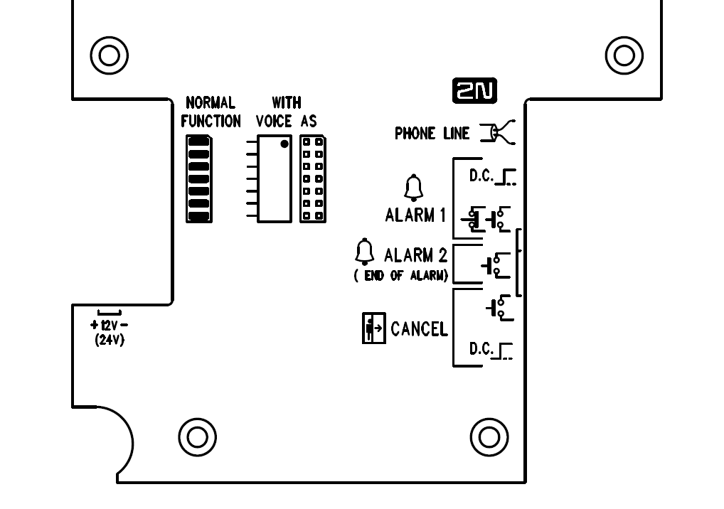
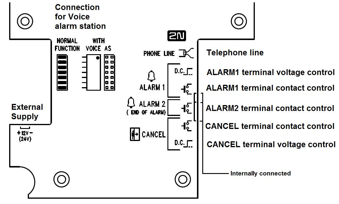
Electrical Installation - Terminals
Connector / NAME | Description | ||
ALARM terminals | DC = voltage control | 5–24 V DC, any polarity | Alarm call activation Activation mode (NO, NC, auto detection) is set by parameter 920. |
N.O. = NO contact / N.C. = NC contact | normally open contact / normally closed contact, if unused, a jumper is mounted | ||
| Alarm 2 | N.O. = NO contact | Press the button shortly (approx. 100 ms) to set up a call to the numbers stored in memories 021–026. Press the button for a long time (approx. 3 s) to end the rescue process if activated (966 = 1,3). | |
CANCEL terminal | voltage control | 5–24 V DC, any polarity | Alarm call deactivation upon door opening |
contact control | any contact | ||
connector | connector mounted | normal function of 2N® Lift1 | 2N® Voice Alarm Station connector |
| interconnection with Voice Alarm Station switch | used for connection of audio units under and above the lift cabin | ||
jumper RECOVERY MODE | recovery mode | Set the jumper to ON to activate the recovery mode for FW upgrade whenever a problem occurs with the 2N® Lift1 – 2N® Service Tool connection. If there is a 2N® Lift1 – 2N® Lift1 Service Tool connection problem, put the jumper on this connector to switch 2N® Lift1 into the recovery mode for firmware upgrade. Connect the button 2 contacts for 5 seconds to reset the factory values. It is equivalent to parameter 999 and can be used if the service password gets lost. (Disconnect 2N® Lift1 from the telephone line and put the jumper on the connector to switch on the recovery mode. Now reconnect the telephone line and connect the contact for button 2 for 5 seconds. The green and yellow LEDs start flashing to indicate configuration recovery.) | |
connector PROGRAMMING CONNECTOR | for 2N® Programming Tool | USB programming tool for | configuration, firmware, voice menu |
| 12V (24V) | DC voltage | After power connection, the Alarm button is backlit. If the rescue feature is activated, then the yellow LED is shining. | |
Note
- Use 5–24 V DC of any polarity for voltage control. However, make sure that the source is backed up against power outage. You can also connect a buzzer or horn in parallel with the ALARM terminal if voltage control is used.
- You can also use the NO contact or voltage presence for CANCEL activation and invert the function using parameter 916 if necessary – NC contact or voltage absence for activation.
- Make sure that the DoorOpen signal is only activated when both the internal and external lift doors are open and the people can leave the cabin safely.
ALARM Connection
 |
ALARM 1
Set alarm 1 using parameter 920 (Alarm button mode). The call is set up to the numbers in memories 011–016.
0 – normally open contact (Alarm is activated by closing the contact or presence of voltage on the input).
1 – normally closed contact (Alarm is activated by opening the contact or absence of voltage on the input).
2 – auto detection (the connected contact type is auto detected upon the next start, the parameter value is then changed to the type detected).
ALARM 2
Alarm 2 is controlled by the closing contact only. The call is set up to the numbers in memories 021–026 (if uncompleted, there is no fall to memories 011–016).
CANCEL
Set Cancel using parameter 916 (CANCEL input inversion).
0 – normally open contact (Cancel is activated by closing the contact or presence of voltage on the input).
1 – normally closed contact (Cancel is activated by opening the contact or absence of voltage on the input).
Warning
- It is impossible to connect multiple devices to a single line!!!
Tip
- The Compact version is very easy to install because the ALARM button, backlit pictograms and induction loop are part of the product. All you have to do is connect a telephone line. The CANCEL input connection is optional.
Alarm 2 (Button 2)
Alarm 2 is not available on the Compact audio unit until HW version 2. It is used for call setup or rescue end.
Short press (approx. 100 ms) – to set up a call to the numbers stored in memories 021–022 (if empty, memories 011–016 are used).
Long press (approx. 3 s) – to end the rescue process if the rescue function is enabled (966 = 1,3). The yellow LED goes off (if Lift1 is fed with 12 V).
Magnet-Controlled Reed Switch
The Compact HW version 2 is equipped with a magnetic reed switch in a glass envelope, which helps activate Alarm 2 or end the rescue process. The behaviour is like with Alarm 2 (button 2). This contact is in a glass envelope (to the right of the hourglass). Application of the magnet sets up a call or terminates the rescue process.
Telephone Line Connection
2N® Lift1 works regardless of polarity and/or line parameters in a wide range (see the Technical Parameters section). It is connected via the LINE terminals. A great advantage is that 2N® Lift1 requires no additional power supply for operation. For details on 2N® Lift1 connection to PSTN, PBX and GSM gateway lines refer to the
2N® Lift1 Connecting Options section.
CANCEL Input Connection (Door Contact, Optional)
The connection is the same as with the Universal version. Follow the instructions included in the Installation – universal version section, The only difference is that the terminal is in the upper position for contact control and in the low position for voltage control as printed on the rear cover at the terminals.
Induction Loop ConnectionIt is unnecessary to install the induction loop. It is integrated in the product, located to the right in the window area and labelled with the prescribed blue pictogram.
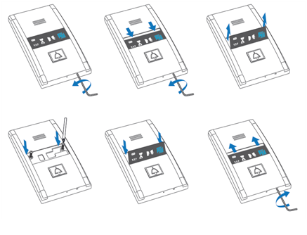
Mounting Completion
Having connected the wires, you can complete the 2N® Lift1 wall mounting. If you can access the cabin wall from the outside, use the mounting type that prevents dismantling and unauthorised tampering from the cabin. Mounting procedure:
- Where access from the outside is possible, use the four pre-drilled M4 holes in the corners.
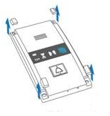
- Remove the corner covers fitted with four M4 screws from behind.
- Screw the 30 mm long M4 headless grub screws included in the audio unit package in place of the corner cover screws removed. Tighten the screws with an internal hexagon key wrench.
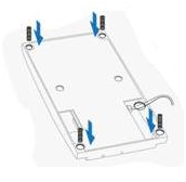
- Put the audio unit on the holes, apply the serrated lock washers from the outside and screw the M4 nuts (both included in the delivery).
- This type of mounting is suitable for lift cabin wall thickness of up to 20 mm.
  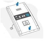 |
If you cannot access the cabin wall from the outside, use the screws under the pictogram glass:
- Insert the hex key wrench (included in the package) in the hole on the product bottom edge and turn it left (about 10 times) until it puts up resistance.
- The window slides down by itself or with little assistance, showing its upper brim.
- Tilt the window forwards and remove it.
- Now you have access to two holes in the window corners. Put 2N® Lift1 on the pre-drilled lift cabin wall holes and fit it with the included screws, which are suitable for plywood, chipboard, laminated plastic etc. walls. For other materials, use appropriate screws or M4 screws in the pre-drilled M4 threaded holes.
Replace the window and insert the hex key wrench in the bottom edge hole turning it right about 10 times until the window slides under the panel edge. Tighten the window applying a moderate force.