2.4 Mounting – Compact Version
Accident Risk
- Make sure that the telephone line is supplied in such a manner that the user cannot touch the wires and is protected against electric accident by a minimum isolation distance of 1.5 mm or isolation of minimum breakdown voltage of 1,500 V.
Prior to Mounting
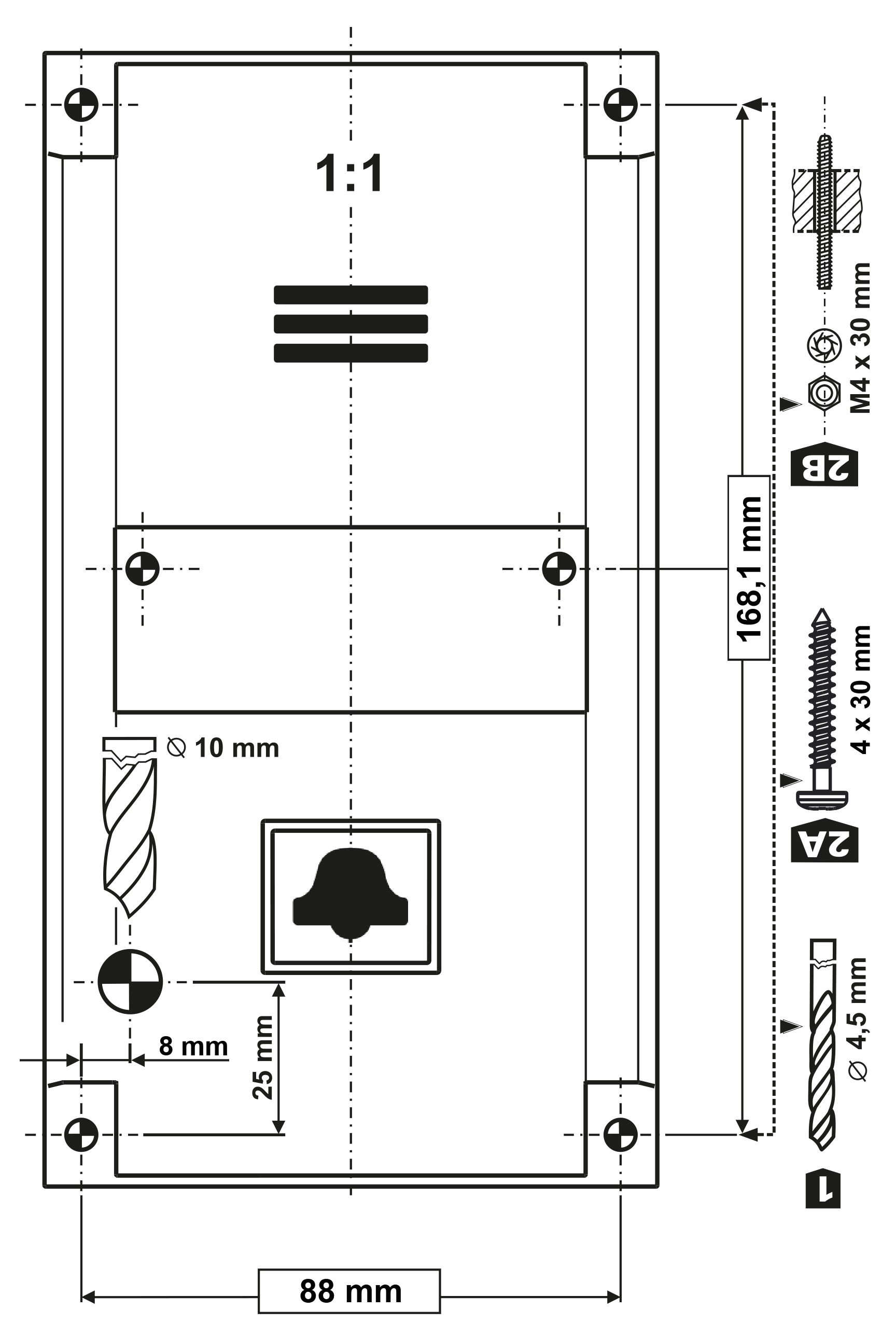
| Mounting Preparation Drill holes into the lift cabin wall according to the selected mounting type. If the cabin wall is accessible from the outside, you can use the corner holes for the M4 screws. If not, use the two holes in the middle for the bolts or make M4 threaded holes. See the 1:1 printing on the product package. The larger hole is intended for cable passage. Round the hole edges to avoid cable damage! |
|
| Mounting The product mounting procedure may not be commenced until all electrical installations have been completed. Remove the connectors, screw the wires and replace the connectors for facilitation. Refer to Mounting Completion for further steps. |

Safety
- The CANCEL, ALARM and Phone terminals and the electronics board are connected to a telephone line where life-endangering voltage may occur. Where switches are connected to the audio unit, make sure while mounting that the minimum isolation distance (from the telephone line connected parts) is 1.5 mm and/or the minimum breakdown voltage is 1,500 V. This applies to the switches too!
- The DC controlled terminals are separated from the telephone line and do not have to meet the isolation requirements mentioned above.
- Make sure that the cables cannot get in contact with sharp edges during installation to avoid insulation damage. Check the minimum isolation distance of 1.5 mm after installation using an isolation meter if possible.
- The manufacturer shall not be held liable for any installations made in conflict with these instructions.