2.3 Electric Installation
This subsection describes how to install the modules, how to connect the 2N® LTE Verso main unit to the power supply and how to connect other elements.
Caution
- The device must be part of the electrical system of the building.
Mounting Preparation
- Unscrew the second module cover on the main unit base.
- Use a flat screwdriver to take out the module cover.
Version A – 2-Module Base
- Place the base on the flush mounting box / predrilled holes with dowels and pull the cables through the bottom holes.
- Insert the metal fitting elements up and down and screw the base plate tight. You can level the base slightly if you are mounting just one base.
Version B – 3-Module Base
- Unscrew the cover of the additional base.
- Use a flat screwdriver to take out the cover.
- Slide the additional base to the main unit base and secure its position with the small side wedges and screws.
- Remove the microphone from the main unit base and loosen the microphone cable.
- Lead the microphone to the third module base as shown in the figure.
- Place the joined bases on the flush mounting box / predrilled holes with dowels and pull the cables through the bottom holes.
Version C – Additional Columns
- Unscrew the cover of the additional bases and take it out with a flat screwdriver.
- Insert the bases into each other as projected and secure their position with the small side wedges and screws.
- Place the cover on the flush mounting box / predrilled holes with dowels and pull the cables if any through the bottom holes.
- Pull the bus using the cable bushing available in the flush mounting box.
Main Unit
LTE Mobile Connection
Insert a PIN-less NanoSIM card (HW version 4 or higher) or MicroSIM (HW version 3 and lower) card with an active data service. The SIM card is not included in the package, so use data services of your preferred LTE provider (the device requires the 4G/LTE technology and cannot be operated in 2G or 3G networks). Connect the antenna provided stuck to the inner blind side. Use an external antenna when mounting another module in the blind position (Part No. 9155048).
SIM card inserting
- How to insert a SIM card:
- HW version 4 and higher
- Insert a NanoSIM card in the SIM slot and push it gently to fit it into position. Repush the card gently to release and partially slide out the card. Now remove the card.
- HW version 3 and lower
- Insert a MicroSIM card in the SIM slot. Remove the card in the same way.
Power Supply Connection
2N® LTE Verso is powered from an external 12 V / 2 A DC source.
External Power Supply
Use a 12 V ±15 % SELV supply dimensioned to the minimum current consumption of 2 A (Part No. 91341481E) to make your system work reliably. This power supply provides 2N® LTE Verso with 24 W for feeding of the main unit and connected modules.
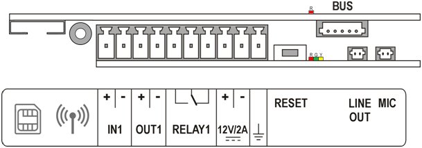
Main Unit Connector Configuration
 |
Caution
- We recommend you to use a grounding cable of the cross-section of 1.5 mm2.
| Legend | |
MicroSIM | MicroSIM card slot |
| MMCX antenna connector | LTE mobile network antenna connector |
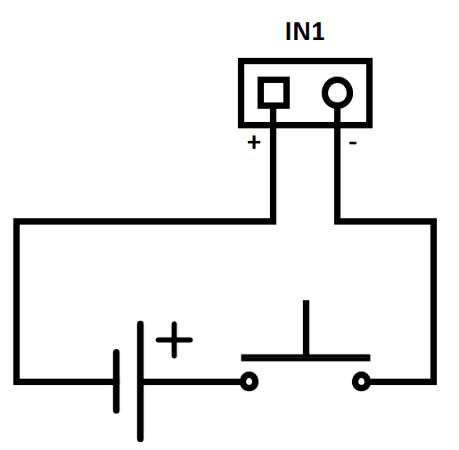
IN1 | IN1 terminals for input in passive/ active mode (−30 V to +30 V DC) OFF = open OR UIN > 1.5 V ON = closed contact OR UIN < 1.5 V |
OUT1 | OUT1 terminals of active input for 2N® Security Relay or electric lock connection 8 up to 12 V DC depending on power supply (PoE: 10 V; adapter: power supply voltage minus 2 V), max 400 mA |
RELAY1 | RELAY1 terminals with accessible 30 V / 1 A AC/DC NO/NC contact. Used for connection of non-critical devices only (lights, e.g.). |
12V/2A | External 12 V / 2 A DC supply terminals |
GND | Grounding terminal |
RESET | RESET / FACTORY RESET button |
RGY | LED indicators (red/green/yellow) |
| R | LED indicator on the upper board (red). Flashing indicates that the provider's network is being searched for. Once the network is connected, the LED stops shining. |
LINE OUT | LINE OUT connector (1 VRMS). Connector type JST SHR-02V-S. |
MIC | MIC connector for microphone connection |
BUS | 2N® IP/LTE Verso bus connector |
Tip
- Output wiring diagram for Relay terminals
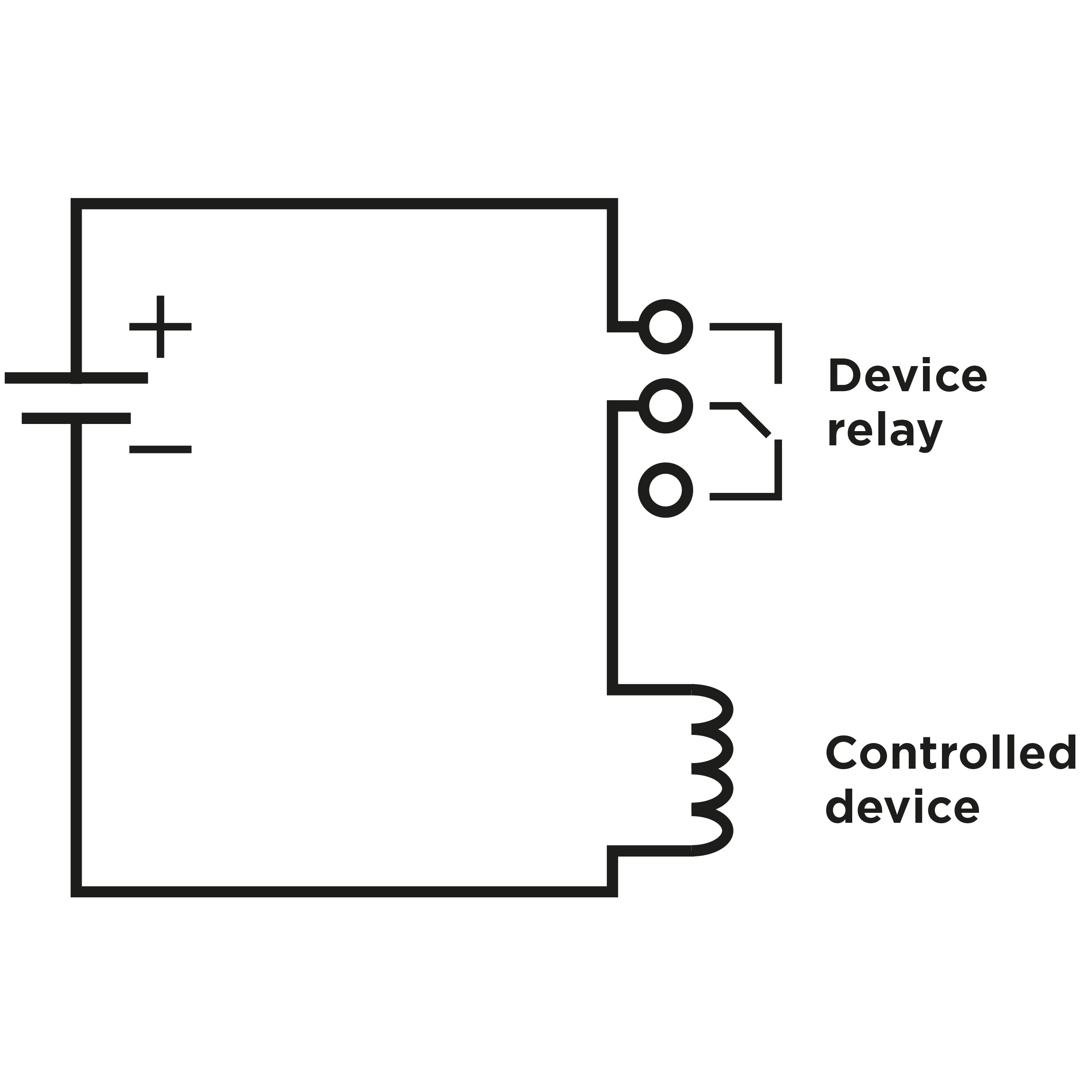 |
Wiring diagram for the controlled device’s electric circuit closing
 |
Wiring diagram for the controlled device’s electric circuit opening
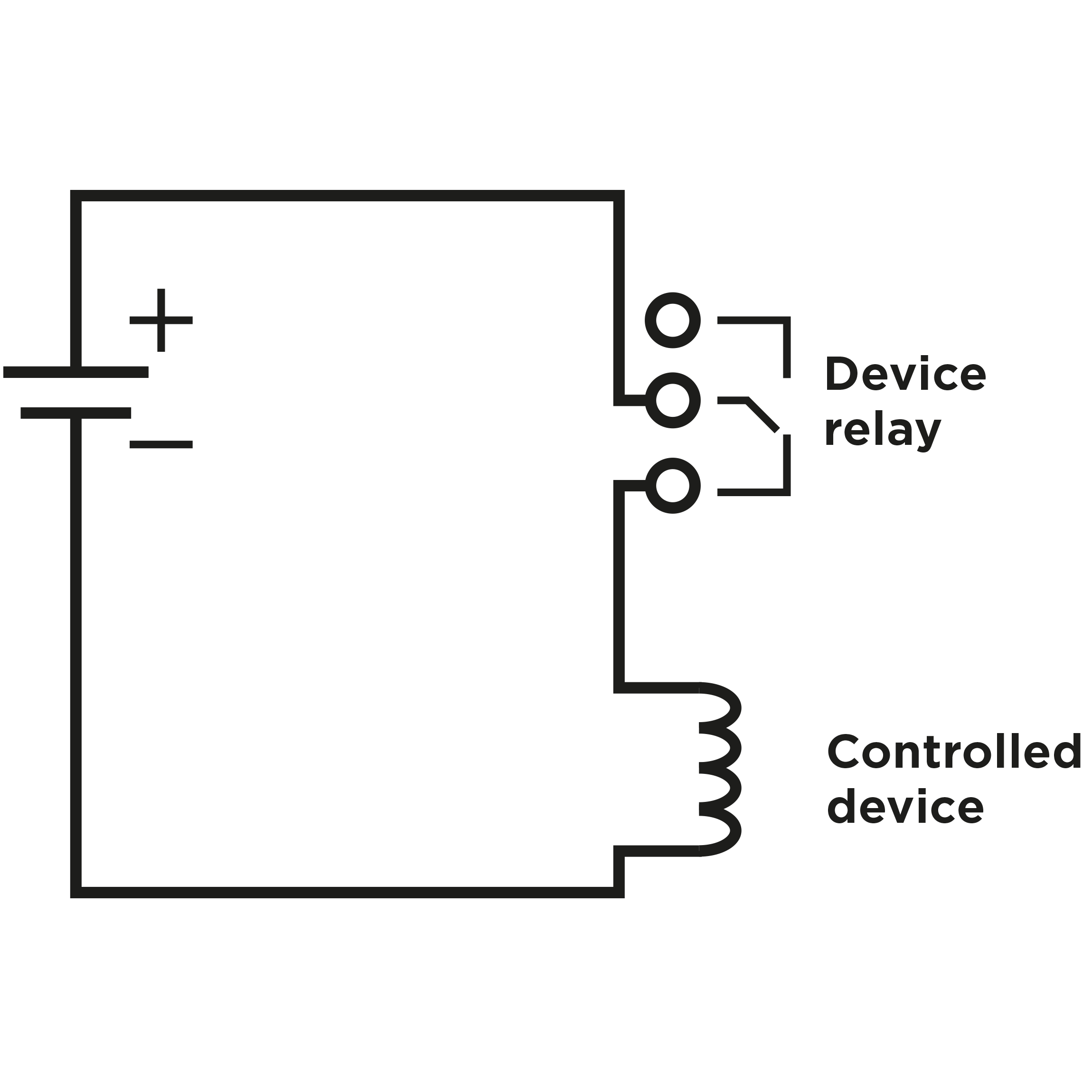
Tip
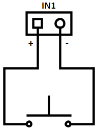
Wiring diagram of IN1 connector in active mode
 |
Wiring diagram of IN1 connector in passive mode
 |
LTE Connection Verification
Having connected the power supply, make sure that 2N® LTE Verso has been connected to the LTE data network successfully. A red LED (R) located to the left of the BUS connector on the upper board provides basic diagnostics: flashing means connecting, if the LED goes off, the device is connected to the data network. If it is illuminated for 5 seconds, there is a SIM card error (SIM not inserted, PIN request enable or no active data service). When this 5s timeout is over, another connection attempt is made and the LED starts flashing again, i.e. the LED does not shine permanently if there is a problem. If it keeps flashing only, the LTE signal is insufficient. In this case, check the area LTE signal coverage and antenna connection. If the LTE signal is low, use an appropriately placed external antenna (optional accessory, Part No. 9155048). Caution – do not stick the external antenna to a metal surface!
You can also use the diagnostic SMS commands described in 3.1 Configuration for troubleshooting.
Reset Button
Located among the main unit connectors, the Reset button helps you reset the factory default values and restart the device.
Factory Reset
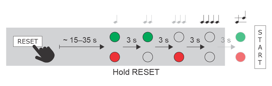
Follow the instructions below to reset the factory default values:
- Press and hold the RESET button.
- Wait until the red and green LEDs go on simultaneously and the acoustic signal
 can be heard (approx. 15–35 s).
 - Wait until the red LED goes off and the acoustic signal
 can be heard (approx. for another 3 s).
 - Wait until the green LED goes off and the red LED goes on again and the acoustic signal
 can be heard (approx. for another 3 s).
 - Wait until the red LED goes off and the acoustic signal
 can be heard (approx. for another 3 s).
 - Release the RESET button.
 |
Note
- The delay after pressing RESET till the first light and sound signalling is set to 15–35 s depending on the 2N IP intercom/answering unit model used.
Caution
- In case of resetting the factory default settings on a device with a version of firmware 2.18 or higher it is necessary to reprogram the 2N® Security Relay using the instructions from section 2.4.
Device Restart
Press the RESET button shortly (< 1 s) to restart the system without changing configuration.
Available Switches
| Location | Name | Description |
|---|---|---|
| Main Unit | Relay 1 | Passive switch: NO/NC contact, up to 30 V / 1 A AC/DC. Used for connection of non-critical devices only (lights, e.g.). |
| Output 1 | Active switch output: 8 up to 12 V DC depending on power supply (power supply voltage minus 2 V), max 400 mA | |
I/O Module* (Part No. 9155034) | ext.relay1 | Passive relay switch: NO and NC contacts, up to 30 V / 1 A AC/DC. Used for connection of non-critical devices only (lights, e.g.). |
| ext.relay2 | Passive relay switch: NO and NC contacts, up to 30 V / 1 A AC/DC. Used for connection of non-critical devices only (lights, e.g.). |
More modules marked by * can be used.
Security
- The 12V output is used for lock connection. If, however, the unit (2N IP Intercom, 2N Access Unit) is installed where unauthorized tampering may happen, we strongly recommend that the 2N® Security Relay (Part No. 9159010) be used for enhanced installation security.
Warning
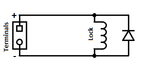
When you connect a device containing a coil, such as a relay or an electromagnetic lock, it is necessary to protect the intercom against voltage peak while switching off the induction load. For this way of protection we recommend a diode 1 A / 1000 V (e.g., 1N4007, 1N5407, 1N5408) connected antiparallel to the device.
 |