2. Express Wizard for Basic Settings
Device Setting
Make sure that your device is properly installed and connected to My2N before logging in to the intercom configuration interface. Log in to My2N at https://my2n.com and add your intercom to the 2N® Remote Configuration. You have to enter your My2N security code during login - find the code in the card provided in the intercom package. Get access to the intercom web configuration interface via the 2N® Remote Configuration.
Use the name admin and password 2n (i.e. default reset password) for your first login to the configuration interface.
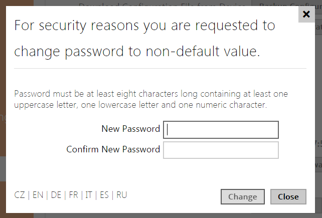
We recommend you to change the default password upon your first login.
The intercom requires a password change upon the first login. Strong passwords are only accepted: eight characters at least including one capital letter, one small letter and one digit.
 |
Firmware Update
We also recommend you to update your intercom firmware upon the first login to the intercom. Refer to www.2n.cz for the latest firmware version. Press the Update Firmware button in the System / Maintenance menu to upload firmware. The intercom will get restarted upon upload and only then the updating process will be complete. The process takes about 30 seconds.
SIP Server Connection Setting
The intercom is automatically configured for making calls via the My2N 2N® Mobile Video service. To use another VoIP infrastructure, set the necessary parameters in the Services / Phone / SIP menu.
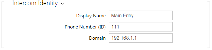 |
- Display name – set the name to be displayed as CLIP on the called party's phone, in the login window and on the web interface start page.
- Phone number (ID) – set the intercom phone number (or another unique ID composed of characters and digits) to identify the intercom uniquely in calls and registration.
- Domain – set the domain name of the service with which the intercom is registered. Typically, it is equivalent to the SIP Proxy or Registrar address. If you do not use a SIP Proxy in your intercom installation, enter the intercom IP address.
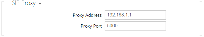
If you use a SIP server (Proxy, Registrar), set the addresses for the following network elements:
 |
 |
- Proxy address – set the SIP Proxy IP address or domain name.
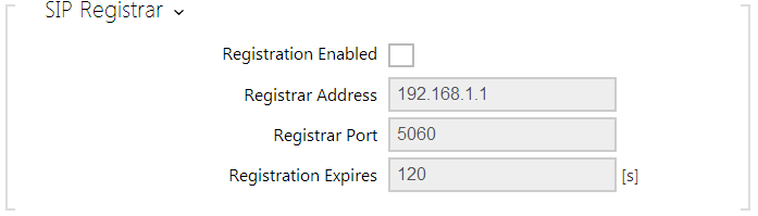
- Registrar address – set the SIP Registrar IP address or domain name. The SIP Proxy and SIP Registrar addresses are usually identical.
- Registration enabled – enable intercom registration with the set SIP Registrar.
If your SIP server requires authentication of terminal equipment, enter the following parameters:
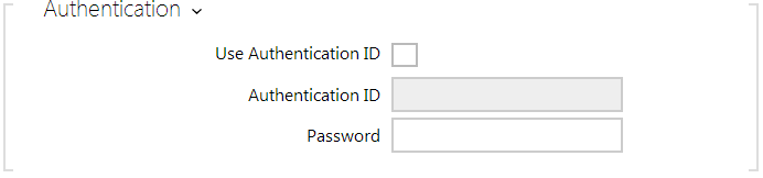 |
- Password – enter the password for intercom authentication.
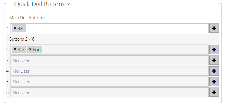
Quick Dial Button Settings
All the 2N LTE intercom models are equipped with quick dial buttons. If you press a quick dial button, a call will be set up to the phone number assigned to the respective Users list position.
In the Hardware / Buttons menu is displayed the list of all potentially available intercom buttons including those physically absent. In some intercom models, the button list is divided into 8/5-item groups corresponding to the button extending modules. Click ![]() , select the user and press Add to add a user to the editing field. To search a user in the list, use the fulltext field and the username. One quick dial button can be shared by multiple users.
, select the user and press Add to add a user to the editing field. To search a user in the list, use the fulltext field and the username. One quick dial button can be shared by multiple users.
 |
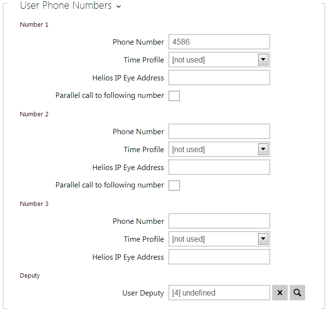 |
You can also use the 2N LTE intercom with one or more IP phones without a SIP server. Use the Direct SIP Call for outgoing calls and enter the called phone SIP address (sip:phone_number@phone_ip_address) instead of the phone number.
Electric Lock Switching Settings
An electric lock can be attached to the 2N LTE intercoms and controlled by a code from the intercom numeric keypad, or a code from the IP phone keypad during a call. Connect the electric lock as instructed in the Installation Manual of your intercom model.
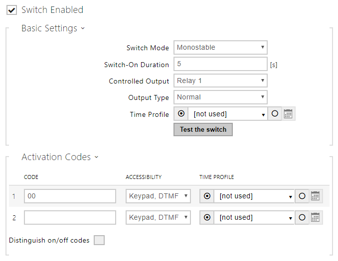 |
Enable the switch in the Switch Enabled parameter in the Hardware / Switches / Switch 1 tab, set the Controlled Output to the intercom output to which the electric door lock is connected. Now set one or more activation codes for the electric door lock switching.