2.2 Mechanical Installation
Content
Flush Mounting - Classic Bricks
Common Mounting Principles
Tip
- Select flush mounting where possible to make your product elegant looking, more vandal resistant and more secure.
Caution
- Stainless steel screws are used for the 2N® IP Uni assembly. Other screws than stainless steel ones corrode soon and may aesthetically deteriorate the surrounding environment!
- Having removed the front panel, make sure that no dirt gets inside the product (especially onto the sealing surface).
Caution
Before starting the mechanical installation on a selected place, make sure carefully that the preparations connected with it (drilling, wall cutting) cannot damage the electrical, gas, water and other existing wires and pipes.
- The warranty does not apply to the product defects and failures arisen as a result of improper mounting (in contradiction herewith). The manufacturer is neither liable for damage caused by theft within an area that is accessible after the attached electric lock is switched. The product is not designed as a burglar protection device except when used in combination with a standard lock, which has the security function.
- When the proper mounting instructions are not met, water might get in and destroy the electronics. It is because the intercom circuits are under continuous voltage and water infiltration causes an electro-chemical reaction. The manufacturer's warranty shall be void for products damaged in this way!
Flush Mounting – Classic Bricks
- (including hollow bricks, thermally insulated walls, etc.)
What you need:
- A properly cut hole
- Plaster, mounting glue, mounting foam or mortar as necessary
 |
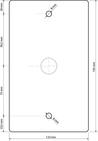
- Cut a wall hole using the template enclosed. Make sure that all the required cables are available in the hole.
- Unpack the plastic mounting box. Break out the cable holes as necessary and make sure that the wall hole is big enough for the box.
- Wall up the mounting box making sure that the box is aligned with the wall surface. Wait until the plaster (mortar, mounting foam, etc.) sets.
- Unscrew the front panel from the door intercom.
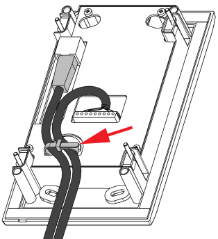
- Connect the cables to the terminals or RJ connector as described in the Electric Connection subsection.
You can use the cable tie for connection as shown:
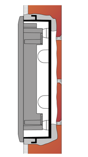
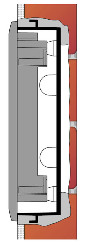
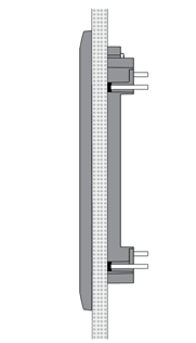
Mounting completion – after electric installation!- Insert the intercom in the mounting box in the wall.
- Tighten the intercom with the stainless steel screws included in the delivery. As the screw holes are oval, you can perfect the vertical position before tightening.
- We do not recommend you to insert the button tags now.
- Replace the stainless steel front panel fixing it with the stainless steel screws you unscrewed in step 4 above.
- Seal the top and lateral sides carefully with some cement or non-aggressive silicone to avoid water infiltration.
 |
Make sure that the installation hole has the required dimensions for flush mounting. Dimensions are shown at the following picture.
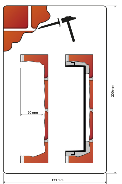 |
Hole dimensions for flush mounting
Flush Mounting – Plasterboard
What you need:
- Just a properly cut hole
 |
Tip
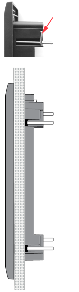
- If this is your first plasterboard installation, check the function of the intercom side clamps. Loosen and then re-tighten the clamp screw to see how it turns automatically and starts moving forwards in its slot. Remember to return the clamp into the original position after the check!
Caution
- Check the plasterboard wall and room interior pressure values (caused, e.g., by overpressure ventilation). If the difference between the values is too great, separate the intercom using, for example, the mounting box enclosed and seal the cable passage to avoid loudspeaker damage.
- Cut a hole 100 (W) × 180 (H) mm.
- Unscrew the front panel from the door intercom.
- Connect the cables in the hole to the terminals or RJ connector as described in the Electric Connection subsection Mounting completion – after electric installation!
- Insert the intercom in the hole keeping it in the vertical position.
- Loosen the four clamp screws one after another and then retighten them slowly. They will turn aside automatically and start moving forwards in their slots. You need about 10 turns to tighten the clamps completely. You can perfect the vertical position before final tightening of the screws.
- We do not recommend you to insert the button tags now.
- Replace the stainless steel front panel fixing it with the stainless steel screws you unscrewed in step 2.
 |
Wall Mounting
- (concrete and steel structures, entry barrier columns, etc.)
What you need:
- Wall mounting box Part No. 9153003
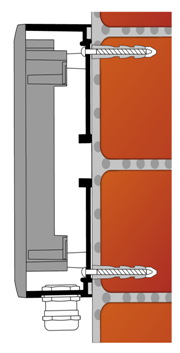 |
The 2N® IP Uni Al box, (Part No. 9153003) is designed for wall mounting especially where flush mounting is impossible such as on carrier elements of industrial objects.
Mounting instructions:
- a) If the cable wall outlets are located directly under the intercom to be installed, move the cap from the middle hole to the bottom one to make way for the cables. Make sure that no water can get into the intercom through the middle hole! The best solution is to seal the hole perfectly with silicone, for example.
b) If the cables lead along the wall below the intercom level, put the template to the wall in its normal position – the bushing will be on the bottom side.
c) If the cables lead along the wall above the intercom level, put the template to the wall reversely – the bushing will be on the upper side. - Use an 8 mm drill to drill two holes of the minimum depth of 50 mm with the aid of the template.
- Push the dowels into the holes and attach the box and screws. Perfect the box position using the oval holes before tightening the screws completely.
- Connect the cables to the intercom as instructed.
- Mount the intercom without the front panel to the box using the M4 screws included in the delivery.
- Screw the front panel onto the intercom.
- Tighten the cable bushing properly to fix the cables especially where the bushing is on the upper box side to avoid water leakage!
 |
Dimension for wall (surface) mounting