2.3 Electric Installation
2N® IP Style can be fed either from an external 12V / 4 A DC power supply or from a PoE+ 802.3at supporting LAN.
External Power Supply
For reliability reasons, use a 12 V ±15% SELV supply dimensioned to the current consumption as required for feeding of the main unit and connected extending modules.
DC voltage [V] | Load [A] | Max power [W] |
|---|---|---|
| 12 | 3 | 36 |
| 12 | 4 | 48 |
PoE+ Supply
2N® IP Style is compatible with the PoE+ 802.3at technology and can be supplied directly from the LAN via compatible network elements. If your LAN does not support this technology, insert a PoE injector, Part No. 91378101, between 2N® IP Style and the nearest network element. This power supply provides 2N® IP Style with 21.6 W for feeding of the main unit and connected modules.
Caution
- The PoE power supply cannot provide 2N® IP Style with a full functionality as it only offers a limited mode (Low Power Mode) for basic configuration. This way of feeding is not recommended. Connect the device to a PoE+ supply or a convenient DC supply and restart the device.
- The PoE power supply detection is performed during the device restart.
- If PoE supply is used and the device works in a low power mode:
- a power problem notification is displayed in all the setting sections,
- the display backlight is limited (to 25% of the programmable brightness value),
- the device status indicating LED on the front side is unfunctional,
- any module connected via the vbus cable is unfunctional.
Combined Power Supply
2N® IP Style can be fed from an external power supply and PoE+ at the same time. In this mode, the maximum power of 48 W (if a 12V / 4A DC external supply is used) or 36 W (if a 12V / 3A DC supply is used) is available for feeding the main unit and connected modules.
Warning
- In case the external power supply is disconnected / fails during the combined external / PoE feeding, the device will get restarted. The device will run in the Low Power Mode and a feeding problem warning will be displayed in all of the configuration sections.
- Reconnect the device to an external power supply or PoE+ and force restart to recover the full functionality.
Main Unit Max Power Overview | |||
|---|---|---|---|
| Main Unit | Consumption [W] (Maximum value) | ||
mA (from 12V supply) | W (from 12V supply) | W (from PoE+) | |
| Idle | 505 | 6.06 | 7.13 |
| Restart | 700 | 8.4 | 9.88 |
| Infrared light (100%) | 655 | 1.8 | 2.12 |
| Display backlight intensity (100%) | 950 | 4.8 | 5.65 |
| Audio (100 %) | 1420 | 10.98 | 12.92 |
| Video motion detection | 20 | 0.24 | 0.28 |
| OUTPUT | 600 | 7.2 | 8.47 |
| RFID ON | 550 | 0.54 | 0.64 |
| Pictogram backlight (100 %) | 570 | 0.24 | 0.28 |
| Video streaming (ON) | 530 | 0.3 | 0.35 |
| CPU (100 %) | 50 | 0.6 | 0.71 |
| Memory (100 %) | 25 | 0.3 | 0.35 |
| GPU (100 %) | 50 | 0.6 | 0.71 |
3 x Stream H.264 (1920 x 1080) MJPEG (1280 x 720) | 50 | 0.6 | 0.71 |
| Maximum Power Consumption | 5 925 | 33.66 | 39.61 |
LAN Connection
2N® IP Style is connected to the Local Area Network (LAN) via the UTP/STP cable (Cat 5e or higher) terminated with an RJ-45 (LAN) connector. As the device is equipped with the Auto-MDIX function, you can use either the straight or crossed cable version.
Caution
- We recommend the use of a LAN surge protection.
- We recommend that an SSTP Ethernet cable with a shielded RJ-45 connector is used, which is connected to the switch (with the grounding option) using the same shielded connector. Thus, the device is grounded without the need to use grounding terminals.
Tip
- Remove the protective connector cover to facilitate the threading of the UTP/STP cable RJ terminal into the device box.
Warning
-
This product cannot be connected directly to the telecommunications lines (or public wireless LANs) of any telecommunication carriers (e.g. mobile communications carriers, fixed communications carriers, or internet providers). In the case of connecting this product to the Internet, be sure to connect it via a router.
Main Unit Connectors
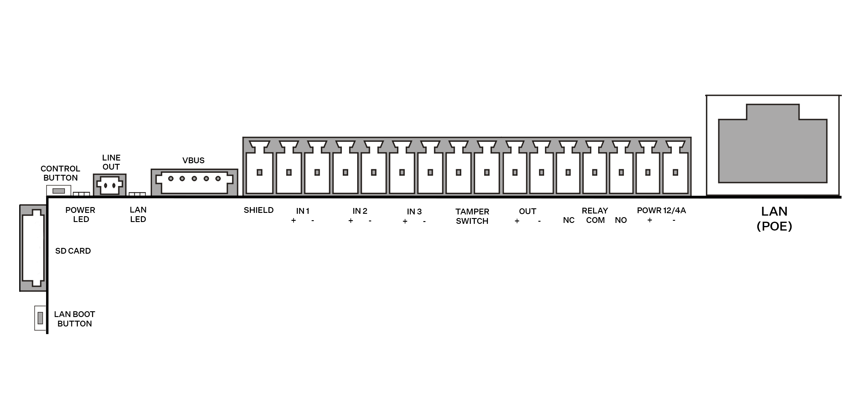 |
Legend to the figure
| |
| LAN BOOT BUTTON | LAN connection restart button |
| SD CARD | SD card slot |
| CONTROL BUTTON | Factory reset button |
| POWER LED | Device status LED |
| LAN LED | LAN connection status LED |
| VBUS | Bus connector |
SHIELD | Grounding terminal |
| IN1, IN2, IN3 | Input terminals in passive / active mode (−30 V to +30 V DC)
|
| TAMPER SWITCH | Security system connecting terminals (on the back side above the connectors) |
| OUT | 12 V / 0.6 A DC active output |
| RELAY | 30 V / 1 A AC/DC NO/NC contact terminals. Used for connection of non-critical devices only (lights, e.g.). |
| POWER 12 V / 4 A | External 12 V / 4 A DC power supply terminals |
| LAN connector | Optionally PoE+ 802.3at for device LAN connection |
| Tamper Switch | Switch detecting unauthorized device opening |
Caution
- We recommend that a grounding cable of the cross-section of 1.5 mm2 is used.
Available Switches
| Location | Name | Description |
|---|---|---|
| Basic Unit | RELAY | Passive switch: make and break contact, up to 30 V / 1 A AC/DC Used for connection of non-critical devices only (lights, e.g.). |
| OUT | Active switch output: 8 to 12 V DC according to power supply (PoE: 10 V; adapter: source voltage minus 2 V), up to 600 mA | |
I/O* Module (Part No. 9155034) | ext. relay1 | Passive switch: make and break contact, up to 30 V / 1 A AC/DC Used for connection of non-critical devices only (lights, e.g.). |
| ext. relay2 | Passive switch: make and break contact, up to 30 V / 1 A AC/DC Used for connection of non-critical devices only (lights, e.g.). |
You can use any number of the modules marked with *.
Tip
Relay output wiring diagram
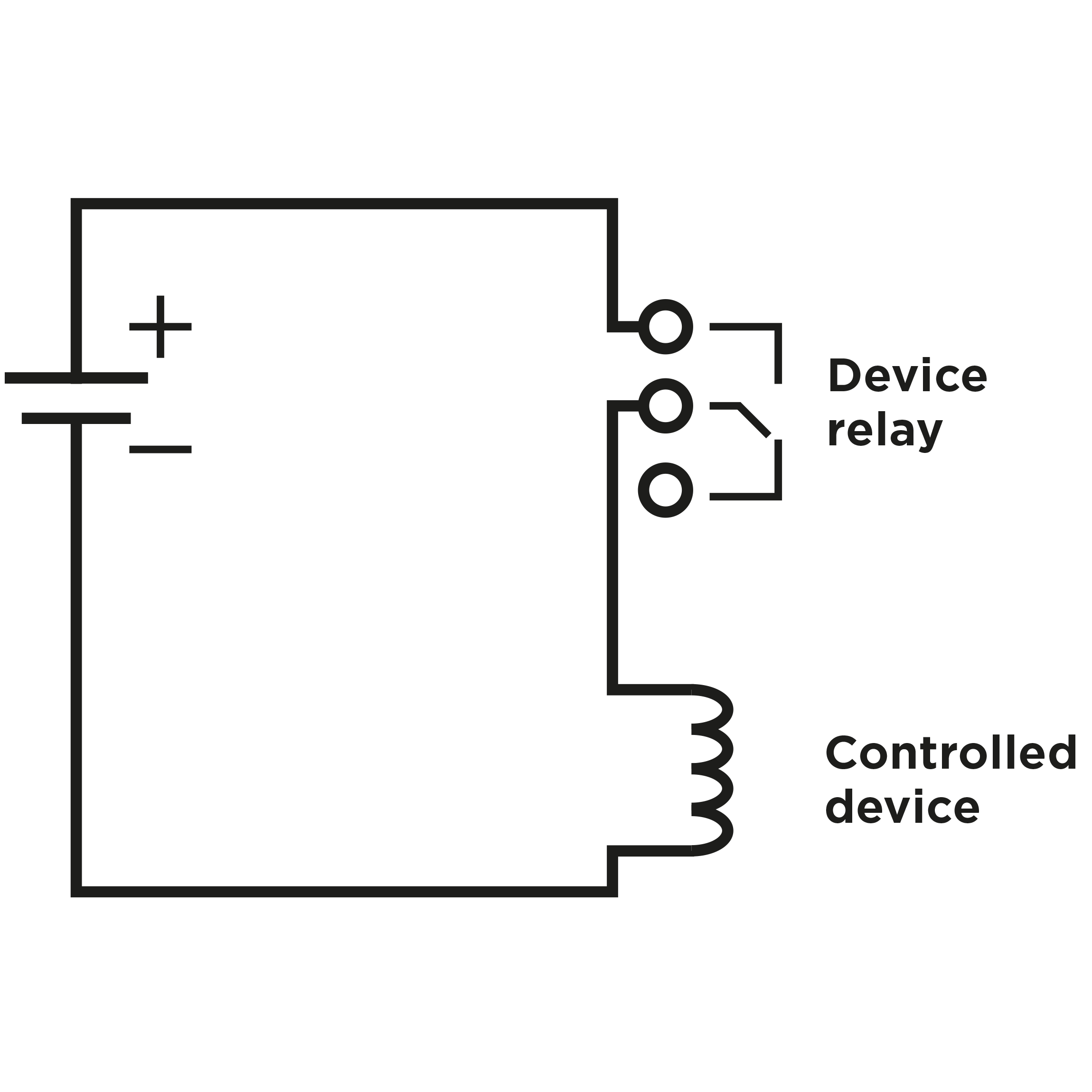
Wiring diagram for making of the electric circuit of the device to be controlled
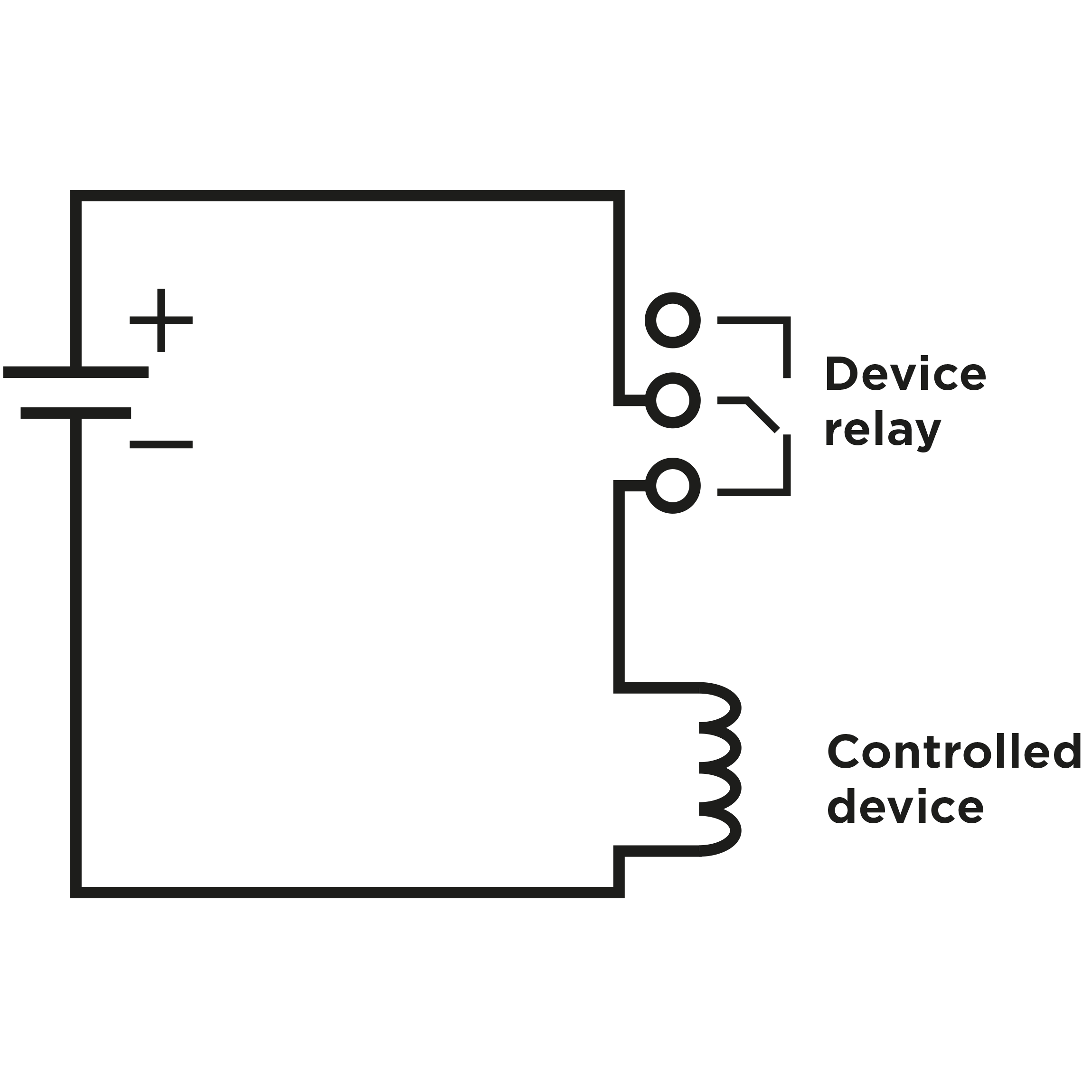
Wiring diagram for breaking of the electric circuit of the device to be controlled
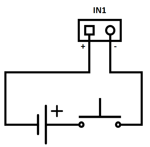
Tip
- Wiring Diagram of IN1 connector in active mode
- Wiring Diagram of IN1 connector in passive mode
 |
Security
- The 12V output is used for lock connection. If, however, the unit (2N IP Intercom, 2N Access Unit) is installed where unauthorized tampering may happen (building envelopes), we strongly recommend that 2N® Security Relay (Part No. 9159010) be used for enhanced installation security.
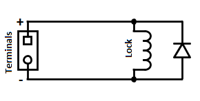
Warning
If a coil containing device is connected, e.g. a relay / electromagnetic lock, it is necessary to protect the intercom output against voltage peak while switching off the induction load. For this way of protection, we recommend a 1 A / 1000 V diode (e.g., 1N4007, 1N5407, 1N5408) connected antiparallel to the device.
 |