2.2 Mechanical Installation
Content
Flush Mounting - Classic Bricks
Flush Mounting - Thermally Insulated Wall
Flush Mounting - Hollow Bricks
Common Mounting Principles
Note
- The recommended standard installation height is 1350 mm from the ground. The installation height may vary depending on the device use.
Tip
- Select flush mounting where possible to make your product elegant looking, more vandal resistant and more secure.
- You can purchase the flush mounting box in advance and hire an installation professional to make the basic installation work. Moreover, the mounting box helps you align the intercom vertically (with a deviation of up to 2°).
Caution
Before starting the mechanical installation on a selected place, make sure carefully that the preparations connected with it (drilling, wall cutting) cannot damage the electrical, gas, water and other existing wires and pipes.
- Make sure that the dowel holes have the required diameter. If the diameter is too large, the dowels may get loose. Use some suitable building adhesive to keep the dowels in place.
- Make sure that the hole depth is sufficient too! The dowel length is 50 mm and the screw length is 90 mm.
- Remember that dowels of poor quality may easily get loose and fall out of the wall!
- Stainless steel screws are used for the 2N® IP Safety assembly. Other screws than stainless steel ones corrode soon and may aesthetically deteriorate the surrounding environment!
- Having removed the front panel, make sure that no dirt gets inside the product (especially onto the sealing surface and microphone sound guides).
Caution
- The warranty does not apply to the product defects and failures arisen as a result of improper mounting (in contradiction herewith). The manufacturer is neither liable for damages caused by theft within an area that is accessible after the attached electric lock is switched. The product is not designed as a burglar protection device except when used in combination with a standard lock, which has the security function.
- When the proper mounting instructions are not met, water might get in and destroy the electronics. It is because the intercom circuits are under continuous voltage and water infiltration causes an electro-chemical reaction. The manufacturer's warranty shall be void for products damaged in this way!
Note
- The microphone sound guides are normally loose after the front panel is removed! The screw is only used as a fall-out protection during installation.
Warning
Be sure keep strictly the hole dimensions while mounting the device into classic bricks without the flush mounting box as shown in the picture with dimensions.
Flush Mounting – Classic Bricks
What You Need:
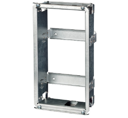
- The brick flush mounting box, Part No. 9151001
- The metal frame, Part No. 9152000
- Hole: (131 x 222 x 82) mm
 |
If you use the brick flush mounting box, follow the instructions below:
- Make a hole using the template.
- Suppose that all the required cables have been carried into the hole.
- Put the intercom inside and place the set onto the hole to make sure that the hole is deep enough and the uneven edge is perfectly covered with the frame.
- If the hole is perfect, wall in the flush mounting box.
- Remove the front panel from the intercom.
- Select the holes for cable supply. Insert the blanks into the other holes. Apply the cable bushings or a suitable sealant to prevent penetration of insects or water. You can also insert the small bushing in the intercom bottom hole.
- Put the frame on the intercom.
- Place the intercom into the flush mounting box while introducing the cables. Leave some of the cables inside the unit as a reserve and the rest under the intercom bottom.
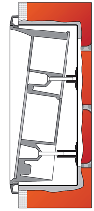
- Insert the supplied screws in the side mounting holes making sure that they penetrate into the flush mounting box nuts. Tighten all the screws properly. Keep the maximum tightening torque of 1.5 Nm. Tip: The screw tightening sequence may affect the intercom position.
- We recommend to seal the frame – wall gap with a silicone or another sealant to avoid wall dampening as a result of water leakage.
- Do not complete mounting until you have finished electrical installation.
Flush Mounting – Thermally Insulated Wall
What You Need:
- Longer screws (depending on the thermal insulation thickness)
- Hole: (135 x 243,5 x 85) mm
Cut out the thermal insulation layer using the template (the same as for classic brick wall).
 |
Caution
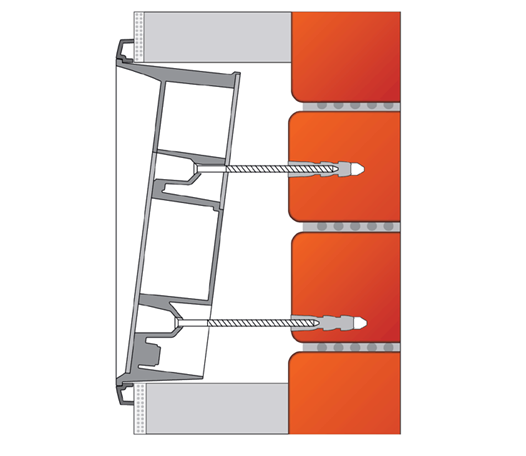
- The hole depth depends on the insulation layer thickness. If the insulation layer is rather thick, you may need longer screws! If there are hollow bricks under the insulation, make sure that your screws pass through the whole dowel (50 mm) and fix the dowel reliably.
- Make sure that the dowel holes have the required diameter. If the diameter is too large, the dowels may get loose. Use some suitable building adhesive to keep the dowels in place.
- Make sure that the hole depth is sufficient too! The dowel length is 50 mm and the screw length is 90 mm.
Suppose that all the required cables have been carried into the drilled hole. Now follow the instructions applicable for classic brick flush mounting. However, remember that thermally insulated walls show less strength than classic brick walls.
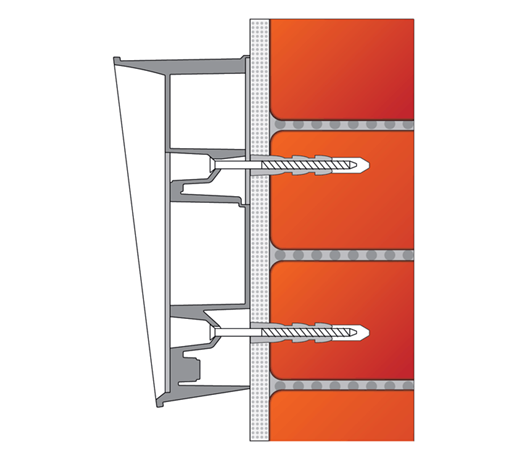
Flush Mounting – Hollow Bricks
What You Need:
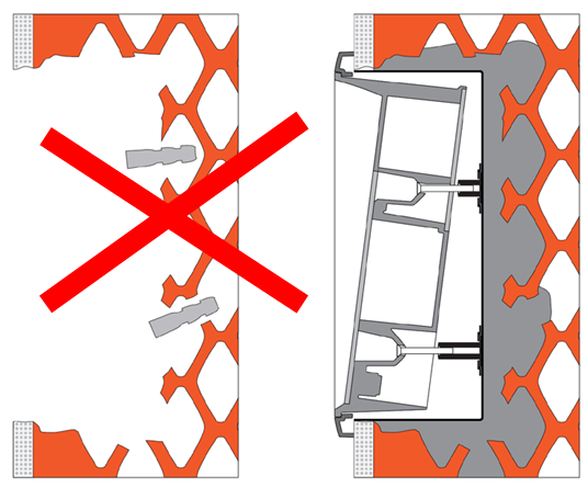
- Brick flush mounting box, Part No. 9151001
- Hole: (131 x 222 x 82) mm
Suppose you intend to install your 2N® IP Safety unit into a wall made of hollow bricks. Note that the external side of the bricks gets damaged by cutting and the dowels cannot practically be fixed into the thin internal part of the bricks. Therefore, use the brick flush mounting box and follow the instructions included therein.
 |
Flush Mounting – Plasterboard
What You Need:
- Plasterboard flush mounting box, Part No. 9151002
- Hole: (116 x 233 x 78) mm
|
Use the plasterboard flush mounting box and follow the instructions included therein.
Wall Mounting
What You Need:
- Just your 2N® IP Safety unit
|
Wall (surface) mounting is used where flush mounting is inapplicable (in concrete and steel structures, entry barrier columns, etc.). The frame is not used.
Caution
- Wall mounting may be a problem where vandals may destroy the unit (in public garages, e.g.). Therefore, use steel fixing elements instead of the dowels and screws included in the delivery.
- Be sure to insert plugs into unused bushing holes to avoid water leakage during facade cleaning, for example. Never leave the holes open for even a short time (one day delay between mounting and cable connection, e.g.).
Warning
- Eliminate the risk of accident! Wall mounting is not suitable for narrow passages or places where people's attention may be distracted. The manufacturer shall not be liable for injuries incurred as a result of unsafe mounting!
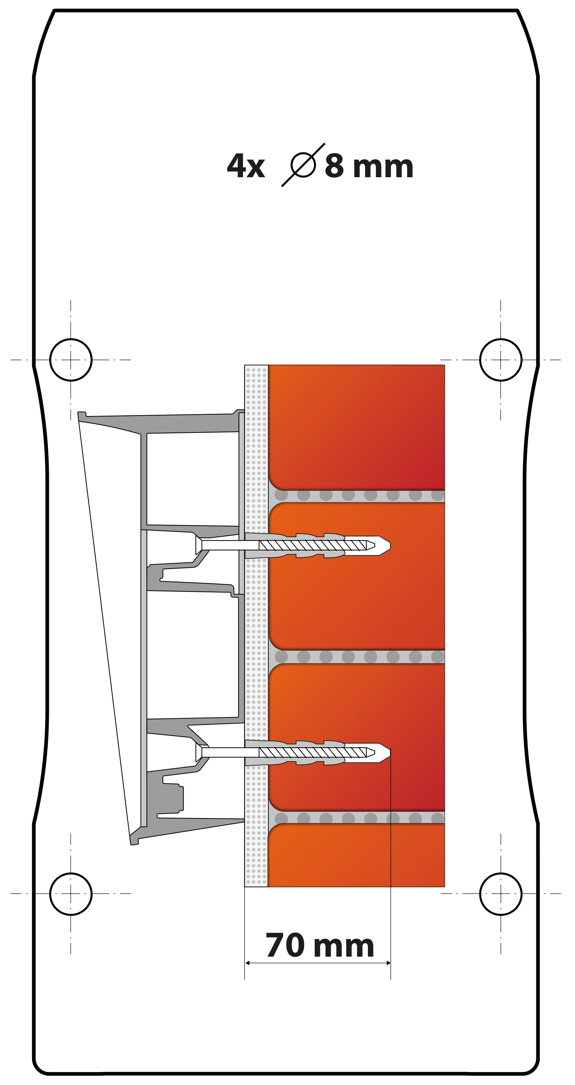
- Select the 2N® IP Safety position with respect to the supply cables. Where the cables are installed inside a structure or wall, use the hole at the intercom bottom.
- Drill holes of the depth of 70 mm for dowels in the wall as shown in the figure. Push or hammer the enclosed dowels into the drilled holes. Use some suitable building adhesive if the dowels are too loose. Use fixing elements of your own for steel structure surface mounting (metric screws + nuts, e.g.).
- Remove the front panel from the intercom.
- Select the holes for cable supply. Select and mount the bushings depending on the cables: 2-hole bushing or 1-hole bushing or both. Insert the blanks in the other holes.
- Put the intercom on the wall/structure while introducing cables inside. Leave some of the cables inside the unit as a reserve. Insert the plugs in the unused bushings and tighten the bushing nuts carefully.
- Do not complete mounting until you have finished electrical installation – refer to Mounting Completion. Where cables lead along the surface, use the bushings included in the delivery.
|
Use of Cable Bushings
The cable bushings included in the 2N® IP Safety delivery are designed for the following cables:
- Big bushing: for two cables of the diameter of 5–6 mm (UTP cable), or, upon insert replacement, for one thick cable/tube of the diameter of up to 14 mm.
- Small bushing: for one cable of the diameter of 5–8 mm.
Tip
- Even a LAN cable including the RJ-45 connector can go through the big bushing. See below for instructions.
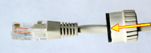
How to Pull a RJ-45 Terminated Cable through a Bushing
1. Unscrew the big bushing nut completely.
 |
2. Remove the sealing including the cover from the bushing. Cut either of the components as shown in the figures.
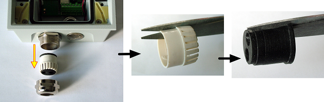 |
3. Put the bushing nut on the cable and insert the sealing.
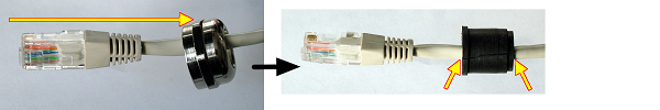 |
4. Replace the cover onto the sealing.
 |
5. Pull the cable connector though the bushing body into the intercom and clip it into the motherboard connector.
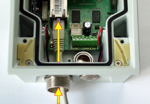 |
6. Move the sealing including the cover along the cable as far as the bushing body, or add a plug if necessary.
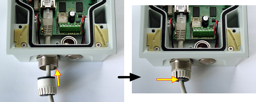 |
7. Replace and tighten the nut.
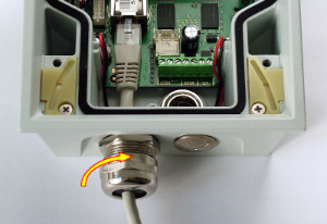 |