2.4 Extending Module Connection
2N® IP Force allows the following extending modules to be connected:
- Additional Switch
- Internal RFID Card Reader 125 kHz
- Internal RFID Card Reader 13.56 MHz
- Internal secured RFID Card Reader 13.56 MHz
- Security Relay
- Wiegand Isolator
- Induction Loop external
- Induction Loop internal
Caution
- In case the firmware versions of the module to be connected and the main unit are incompatible, the module will not be detected. Therefore, it is necessary to update the device firmware after the modules are connected. Use the device web interface in the System > Maintenance > System configuration section for firmware upgrade (see Configuration manual for 2N IP intercoms).
Additional Switch
The Additional Switch (Part No. 9151010) is used for extending the number of inputs/outputs. This extending module is intended for mounting into the 2N® IP Force main unit and is compatible with the basic units with Part No. 915110xxxxx. If the Additional Switch is installed, it is not possible to install Internal RFID Card Reader.
 |
Function:
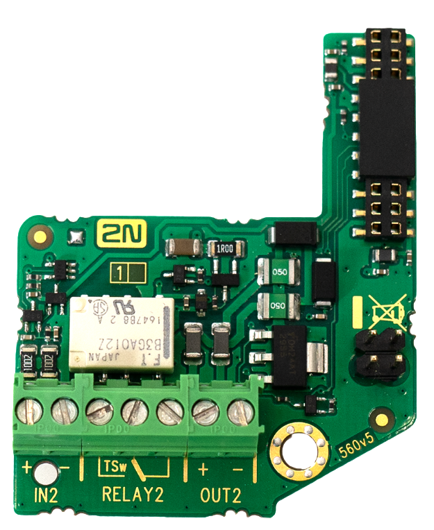
The 2N® IP Force Additional Switch adds two additional switches, one logical input and a tamper switch to the 2N® IP Force basic unit. The purpose of the tamper switch is to signal any unauthorised opening of the intercom (to prevent a theft, e.g.). It is recommended to use the tamper switch.
Specifications version 5:
- IN2 terminals for input in passive / active mode (-30 V to +30 V DC)
- OFF = open OR UIN > 1.5 V
- ON = closed contact OR UIN < 1.5 V
- RELAY2 terminals 30 V/1 A AC/DC NO/NC contact
- OUT2 active output: 12 V/600 mA DC
- Tamper switch input (X2): 24 V/50 mA AC/DC
Specifications version 4 a lower:
- Passive switch: NO and NC contacts, up to 30 V / 1 A AC/DC
- Active switch output: 9 V (Using PoE) or power supply voltage minus 1 V, from 9 to 13 V max. 700 mA DC
- Tamper switch: 24 V / 50 mA AC/DC
Module mounting:
- Switch off the intercom.
- Remove the front panel from the intercom.
- According to your model
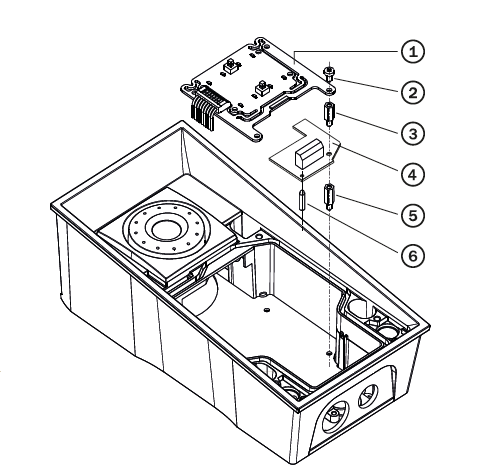
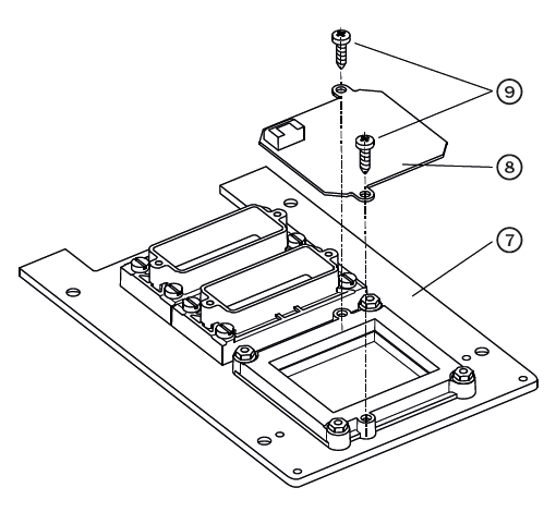
- If you are mounting the switch into a two-nameplate model, demount the button PCB (1) and remove the right-hand bottom spacer (there are four PCB fitting spacers altogether).
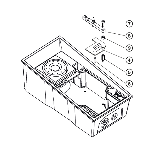
- If you are mounting the switch into a keypad model, take the keypad out of the holder. Demount the right-hand keypad holder – beam with a pin (8) – remembering its position. Demount the right-hand bottom spacer. Do not disconnect the keypad cable!
- If you are mounting the switch into a model other than the two ones mentioned in items 3a and 3b above, remove the right-hand bottom screw from the main board.
- Now screw the enclosed 12 mm spacer (5) into the vacated main board slot.
- Mount the enclosed plastic support (6) onto the switch board bottom side.
- Put the switch board (4) in the main board connector making sure that the screw hole is directly above the spacer.
- According to your model
- If you are mounting the switch into a two-nameplate model, fit the switch board with the enclosed 10.5 mm spacer (3) and reinstall the button PCB (1).
- If you are mounting the switch into a keypad model, reinstall the beam (8) of the keypad holder (the slot is on top). Insert the enclosed 4.5 mm washer (9) between the beam and the switch board, fitting the assembly with the 15 mm screw enclosed (7).
- If you are mounting the switch into a model other than the two ones mentioned in items 7a and 7b, fit the switch board with the original 6 mm screw (2).
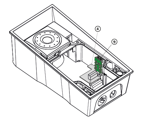
- If you want to use the tamper switch, insert the tamper board (9) in the connector located in the right-hand bottom part of the switch board (4). As the tamper switch shares the relay output (NO and NC) terminals, you cannot use the RELAY2 output with the tamper switch together.
- Place front panel back and tighten all four screws.
 |
 |
 |
Module settings:
Refer to the Configuration Manual for details.
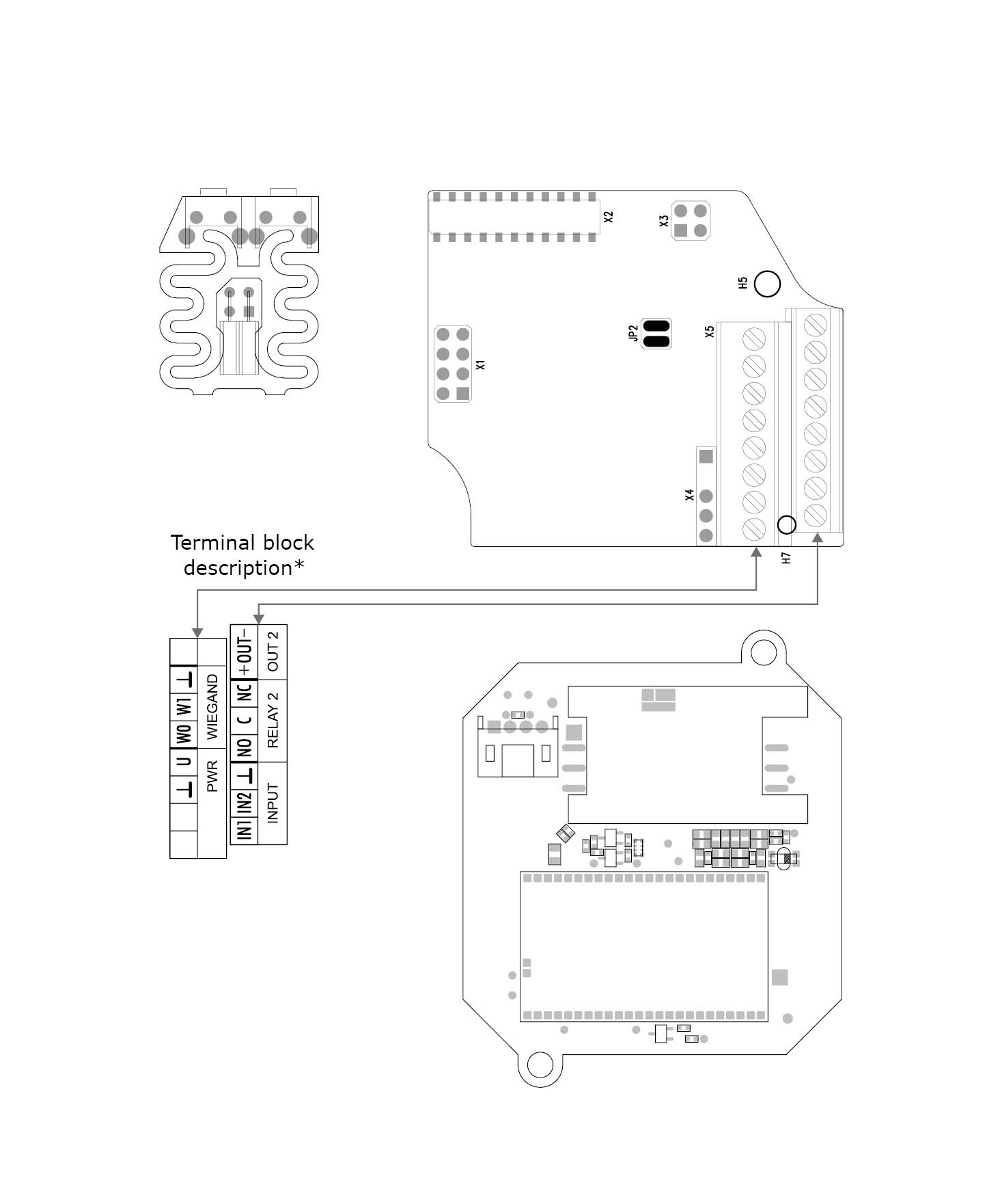
Connection:
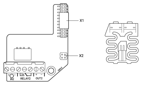 |
Version 5
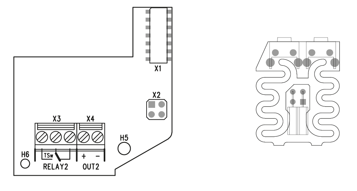 |
Version 4 and lower
Internal RFID Card Reader 125 kHz
The Internal RFID Card Reader 125 kHz (Part No. 9151011) is used for reading RFID card Ids in the 125 kHz band. This module is intended for mounting into the 2N® IP Force model 9151102CR, 9151102R, 9151101CRP and 9151101RP. These models have an window, which is necessary for antenna operation. If the Internal RFID Card Reader is installed, it is not possible to install the Additional Switch.
 |
Function:
The 2N® IP Force Internal RFID Card Reader adds two logical inputs, two additional switches and a tamper switch to the 2N® IP Force basic unit.
The purpose of the tamper switch is to signal any unauthorised opening of the intercom (to prevent a theft, e.g.). It is recommended to use the tamper switch.
Specifications:
Card reader
- Compatible with:
- EM4xxx
- Operating frequency: 125 KHz
- Minimum reading distance: 10 mm above 2N® IP Force cover
Relay output
- Switching contact
- 30 V / 2 A AC/DC
Active output
- 9 to 12 V / 700 mA transistor switched output
Logical inputs
Active mode – requires external voltage (JP2 jumper OFF)
- UIN-ON = min +2.5 V
- UIN-OFF = max +1.5 V
- UIN max = +48 V
- IIN (UIN +48 V) = max 1 mA
Passive mode – requires external contact only (JP2 jumper ON)
- UOUT = approx. 8.3 V
- ILOOP = approx. 0.5 mA
Signalling output
- Internal red LED under reader window
WIEGAND interface
- Off/Input/Output (as programmed)
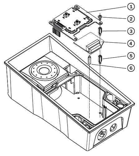
Mounting guide:
- Switch off the intercom.
- Remove the front panel (7) from the intercom.
- Mount antenna board (8). Use two enclosed self tapping screws (9).
- Plug enclosed cable (11) to the antenna board connector.
- Demount a button PCB (1). Don't disconnect its cable!
- There will stay four spacers after the switch board removal. Dismount the bottom right one.
- There are two short metal spacers enclosed to the reader. Take a longer one (5), 12 mm long. Screw it into the free hole.
- Plug an enclosed plastic support (6) to the reader board from the bottom side.
- Put the reader board (4) in the main board connector making sure that the mounting hole is directly above the spacer.
- Screw in a remaining metal spacer (3), 10.5 mm long.
- Fit the button PCB (1) back to its position using original bolts (2).
- If you want to use the tamper switch (to detect unauthorized opening the case, as a theft protection), insert the tamper board (10) in the connector located in the right-hand bottom part of the reader board (4). As the tamper switch shares the relay output (NO and NC) terminals, you cannot use the RELAY2 output with the tamper switch at the same time.
- Plug the antenna cable (11) to its connector at the reader board (4).
- Place front panel back and tighten all four screws.
|
 |
 |
Module setting:
Refer to the Configuration Manual for details of Wiegand, outputs and reader. Refer to the Automation manual for details of input, red LED and tamper function and use.
Connection:
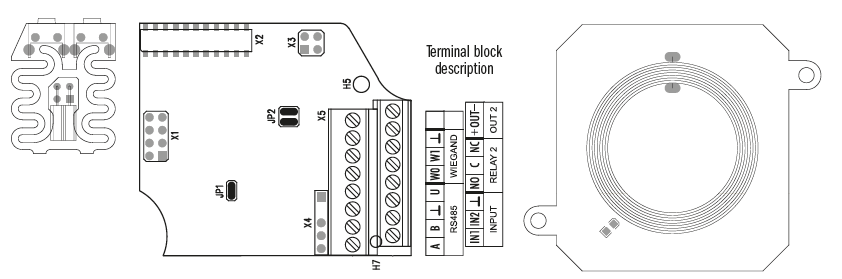 |
| Wiegand Input Technical Parameters | |
|---|---|
| Current | 5 mA |
| Input resistance | 680 Ohm |
| Pulse length | 50 μs |
| Delay between pulses | approx. 2 ms |
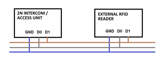 |
Recommended Wiring Diagram for Reader with Bus Driver
 |
| Recommended Wiring Diagram for Reader with Open Collector (OC) Output |
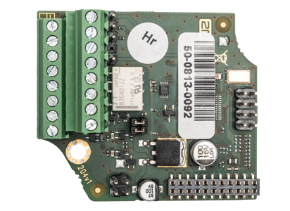
Internal RFID Card Reader 13.56 MHz
The Internal RFID Card Reader 13.56 MHz (Part No. 9151031/9151017) is used for reading RFID card Ids in the 13.56 MHz band, NFC supported. This module is intended for mounting into the 2N® IP Force model 9151101RPW, 9151101CHRPW, 9151102RW and 9151102CHRW. These models have an window, which is necessary for antenna operation. If the Internal RFID Card Reader is installed, it is not possible to install the Additional Switch.
|
9151031
|
9151017
Function:
The 2N® IP Force Internal RFID Card Reader adds two logical inputs, two additional switches and a tamper switch to the 2N® IP Force basic unit.
The purpose of the tamper switch is to signal any unauthorised opening of the intercom (to prevent a theft, e.g.). It is recommended to use the tamper switch.
Specifications:
Card reader
- Operating frequency: 13.56 MHz
- Minimum reading distance: 30 mm above 2N® IP Force cover
RFID Reader 9151031 is compatible with cards (only card serial number is read):
- ISO14443A (MIFARE DESFire)
- PicoPass (HID iClass)
- FeliCa
- ST SR(IX)
- 2N® Mobile Key
- RFID Reader 9151017 is compatible with cards (only card serial number is read):
- ISO14443A (MIFARE DESFire)
- PicoPass (HID iClass)
- FeliCa
- ST SR(IX)
- 2N® Mobile Key
Relay output
- Switching contact
- 30 V / 2 A AC/DC
Active output
- 9 to 12 V / 700 mA transistor switched output. Depends on power supply (PoE: 9 V or power supply voltage minus 1 V).
Logical inputs
Active mode – requires external voltage (JP2 jumper OFF)
- UIN-ON = min +2.5 V
- UIN-OFF = max +1.5 V
- UIN max = +48 V
- IIN (UIN +48 V) = max 1 mA
Passive mode – requires external contact only (JP2 jumper ON)
- UIN1 = approx. 8.3 V
- UIN2 = approx. 8.3 V
- ILOOP = approx. 0.5 mA
Signalling output
- Internal red LED under reader window
PWR
- For external RFID card reader
- Out: 9 to 12 V / 350 mA depends on power supply
WIEGAND interface
- Off/Input/Output (as programmed)
Mounting guide:
- Switch off the intercom.
- Remove the front panel (7) from the intercom.
- Mount antenna board (8). Use two enclosed self tapping screws (9).
- Plug enclosed cable (11) to the antenna board connector.
- Demount a button PCB (1). Don't disconnect its cable!
- There will stay four spacers after the switch board removal. Dismount the bottom right one.
- There are two short metal spacers enclosed to the reader. Take a longer one (5), 12 mm long. Screw it into the free hole.
- Plug an enclosed plastic support (6) to the reader board from the bottom side.
- Put the reader board (4) in the main board connector making sure that the mounting hole is directly above the spacer.
- Screw in a remaining metal spacer (3), 10.5 mm long.
- Fit the button PCB (1) back to its position using original bolts (2).
- If you want to use the tamper switch (to detect unauthorized opening the case, as a theft protection), insert the tamper board (10) in the connector located in the right-hand bottom part of the reader board (4). As the tamper switch shares the relay output (NO and NC) terminals, you cannot use the RELAY2 output with the tamper switch at the same time.
- Plug the antenna cable (11) to its connector at the reader board (4).
- Place front panel back and tighten all four screws.
 |
|
|
Module setting:
Refer to the Configuration Manual for details of Wiegand, outputs and reader. Refer to the Automation manual for details of input, red LED and tamper function and use.
Connection:
 |
Internal secured RFID Card Reader 13.56 MHz
The Internal RFID Card Reader 13.56 MHz (Part No. 9151031S/9151019) is used for reading RFID card Ids in the 13.56 MHz band, NFC supported. This module is intended for mounting into the 2N® IP Force model 9151101RPW, 9151101CHRPW, 9151102RW and 9151102CHRW. These models have an window, which is necessary for antenna operation. If the Internal RFID Card Reader is installed, it is not possible to install the Additional Switch.
 |
9151019
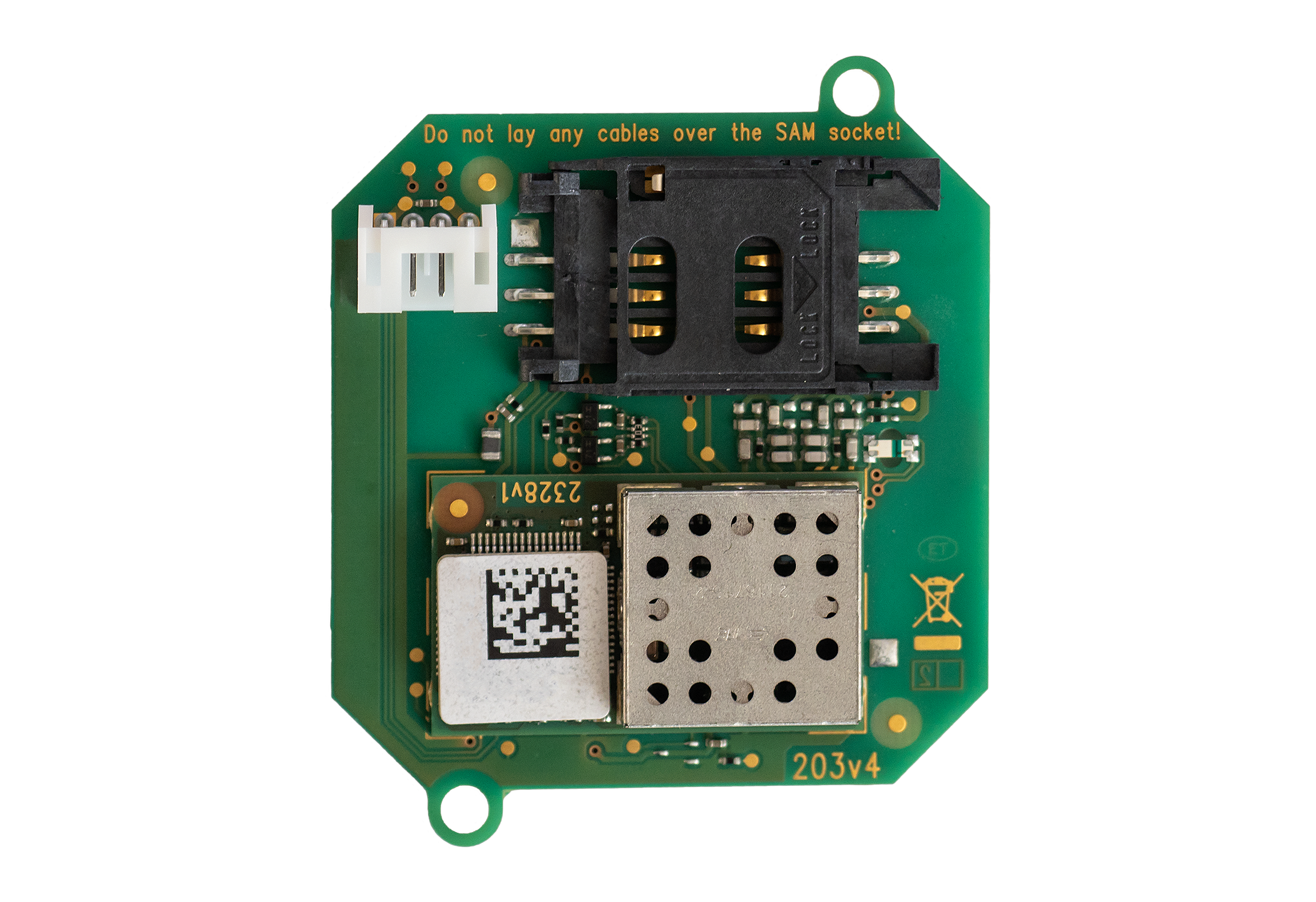 |
9151031S
Function:
The 2N® IP Force Internal RFID Card Reader adds two logical inputs, two additional switches and a tamper switch to the 2N® IP Force basic unit.
The purpose of the tamper switch is to signal any unauthorised opening of the intercom (to prevent a theft, e.g.). It is recommended to use the tamper switch.
Specifications:
Card reader
- Operating frequency: 13.56 MHz
- Minimum reading distance: 30 mm above 2N® IP Force cover
- RFID card reader 9151031S is compatible with cards (optionally card serial number or PAC ID is read):
- ISO14443A (MIFARE DESFire)
- PicoPass (HID iClass)
- FeliCa
- ST SR(IX)
- 2N® Mobile Key
HID SE (Seos, iClass SE, MIFARE SE)
RFID card reader 9151019 is compatible with cards (optionally card serial number or PAC ID is read):
- ISO14443A (MIFARE DESFire)
- PicoPass (HID iClass)
- FeliCa
- ST SR(IX)
- 2N® Mobile Key
HID SE (Seos, iClass SE, MIFARE SE)
Relay output
- Switching contact
- 30 V / 2 A AC/DC
Active output
- 9 to 12 V / 700 mA transistor switched output. Depends on power supply (PoE: 9 V or power supply voltage minus 1 V).
Logical inputs
Active mode – requires external voltage (JP2 jumper OFF)
- UIN-ON = min +2.5 V
- UIN-OFF = max +1.5 V
- UIN max = +48 V
- IIN (UIN +48 V) = max 1 mA
Passive mode – requires external contact only (JP2 jumper ON)
- UIN1 = approx. 8.3 V
- UIN2 = approx. 8.3 V
- ILOOP = approx. 0.5 mA
Signalling output
- Internal red LED under reader window
PWR
- For external RFID card reader
- Out: 9 to 12 V / 350 mA depends on power supply
WIEGAND interface
- Off/Input/Output (as programmed)
Mounting guide:
- Switch off the intercom.
- Remove the front panel (7) from the intercom.
- Mount antenna board (8). Use two enclosed self tapping screws (9).
- Plug enclosed cable (11) to the antenna board connector.
- Demount a button PCB (1). Don't disconnect its cable!
- There will stay four spacers after the switch board removal. Dismount the bottom right one.
- There are two short metal spacers enclosed to the reader. Take a longer one (5), 12 mm long. Screw it into the free hole.
- Plug an enclosed plastic support (6) to the reader board from the bottom side.
- Put the reader board (4) in the main board connector making sure that the mounting hole is directly above the spacer.
- Screw in a remaining metal spacer (3), 10.5 mm long.
- Fit the button PCB (1) back to its position using original bolts (2).
- If you want to use the tamper switch (to detect unauthorized opening the case, as a theft protection), insert the tamper board (10) in the connector located in the right-hand bottom part of the reader board (4). As the tamper switch shares the relay output (NO and NC) terminals, you cannot use the RELAY2 output with the tamper switch at the same time.
- Plug the antenna cable (11) to its connector at the reader board (4).
- Place front panel back and tighten all four screws.
|
|
|
Module setting:
Refer to the Configuration Manual for details of Wiegand, outputs and reader. Refer to the Automation manual for details of input, red LED and tamper function and use.
Connection:
 |
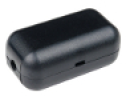
Security Relay
The 2N® Security Relay (Part No. 9159010) is used for enhancing security between the intercom and the connected electric lock. The 2N® IP Security Relay is designed for any 2N IP intercom model with firmware versions 1.15 and higher. It significantly enhances security of the connected electric lock as it prevents lock opening by forced intercom tampering.
 |
Function:
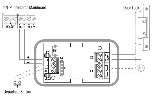
The 2N® Security Relay is a device installed between an intercom (outside the secured area) and the electric lock (inside the secured area). The 2N® Security Relay includes a relay that can only be activated if the valid opening code is received from the intercom.
Specifications:
Passive switch: NO and NC contacts, up to 30 V / 1 A AC/DC
Switched output:
- Where the security relay is fed from the intercom, 9 to 13 V DC is available on the output depending on the power supply (PoE: 9 V; adapter: source voltage of minus 1 V) / 400 mA DC.
- Where the security relay is fed from an external power supply, 12 V / 700 mA DC is available on the output.
Dimensions: (56 x 31 x 24) mm
Weight: 20 g
Installation:
Install the 2N® Security Relay onto a two-wire cable between the intercom and the electric lock inside the area to be secured (typically behind the door). The device is powered and controlled via this two-wire cable and so can be added to an existing installation. Thanks to its compact dimensions, the device can be installed into a standard mounting box.
Connection:
Connect the 2N® Security Relay to the intercom as follows:
- To the intercom active output (OUT1 or OUT2 if a reader module or additional switch is connected)
Connect the electric lock to the 2N® Security Relay output as follows:
- To the switched output.
- To the passive output in series with the external power supply.
The device also supports a Departure button connected between the ‘PB’ and ‘- HeliosIP/IP intercom’ terminals. Press the Departure button to activate the output for 5 seconds.
Status signalling:
| Green LED | Red LED | Status |
|---|---|---|
| blinking | off | Operational mode |
| on | off | Activated output |
| blinking | blinking | Programming mode – waiting for initialisation |
| on | blinking | Error – wrong code received |
Configuration:
- Connect the 2N® Security Relay to the properly set intercom switch output; refer to the Configuration Manual. Make sure that one LED at least on the 2N® Security Relay is on or blinking.
- Press and hold the 2N® Security Relay Reset button for 5 seconds to put the device in the programming mode (both the red and green LEDs are blinking).
- Activate the intercom switch using the keypad, telephone, etc. The first code sent from the intercom will be stored in the memory and considered valid. After code initialisation, the 2N® Security Relay will pass into the operational mode (the green LED is blinking).
Caution
- In case of resetting the factory default settings on a device with a version of firmware 2.18 or higher it is necessary to reprogram the
2N® Security Relay using the instructions above.
Connection:
 |
Tip
Video Tutorial: Security Relay Installation and Configuration
Wiegand Isolator
The 2N® Wiegand Isolator (Part No. 9159011) is used for galvanic isolation of the Wiegand bus.
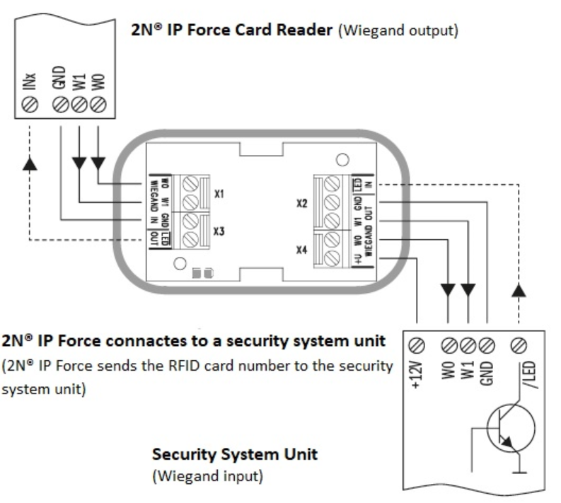
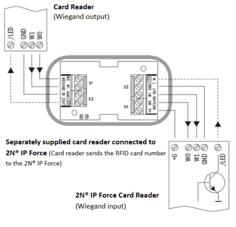
The 2N® Wiegand Isolator is designed for galvanic isolation of two devices with separate power supply and interconnected via the Wiegand bus. The 2N® Wiegand Isolator protects the interconnected devices against communication errors and/or damage.
Connection of the 2N IP intercoms Card Reader to a security system unit is a typical example of application.
 |
Function:
The 2N® Wiegand Isolator separates galvanically a two-wire Wiegand bus in one direction and a status LED signal in the other direction. The module is power supplied from the Wiegand bus receiver side.
Specifications:
- 2-wire WIEGAND IN
- 2-wire WIEGAND OUT
- LED IN switched against GND on WIEGAND OUT side
- Open LED OUT switched against GND on WIEGAND IN side (up to 24 V / 50 mA)
- 5 to 16 V / 10 mA power supply from Wiegand bus receiver side
- 500 V DC isolation strength
Connection:
 |
 |
Induction Loop external
2N® Induction Loop (Part No. 9159050 – Induction loop amplifier for 2N IP intercom, Part No. 9159054 – Induction loop amplifier without 2N IP intercom accessory, Part No. 9159052 – 12 V DC power adapter) is part of sound system installations for hearing impaired persons that are equipped with a special hearing aid capable of receiving reproduced sound via a magnetic field receiver. The system is defined by the IEC 60118-4 standard.
Installation:
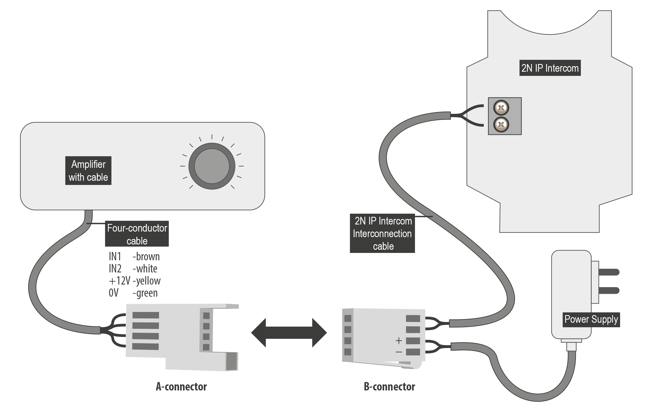
The induction loop amplifier can be wall mounted with the use of an internal induction loop where a signal covering is requested. Outdoor use is possible thanks to the IP65 covering. A four-wire cable of the length of one meter is mounted to the supplied product for easier connection to the intercom. In the cable are two wires for 12 V DC supply and two wires for signal input, the wires are connected into interconnection connector. If you shorten the cable, follow the colour marking.
Before wall mounting run the cable through the hole that you have prepared. Then mark two mounting holes on the wall, through the amplifier front. Remove the amplifier and drill the mounting holes. Use the plugs and screws included in the delivery. Use a drill of the diameter of 6 mm. After fastening, cover the screws with the blanks supplied.
Use the supplied connectors to connect the amplifier to the intercom and power supply. The A connector is connected to the amplifier four-wire cable. Insert a special intercom-connecting cable supplied with the amplifier and 12 V power supply outlets to the B connector. Connect the special cable to the intercom and connect the power supply to the mains. You can place the mated A and B connectors into the 2N IP intercom cover. The connectors help you connect stripped cables. Open the connector by pushing a thin screwdriver onto the white spots at its front and close the connector by sliding the movable part through a side gap.
Finally, test the amplifier function using a suitable receiver for hearing impaired persons or magnetic field communication tester. No other settings are required.
 |
Specifications:
- Supply voltage: 8 18 V DC
Supply current at 12 V supply:
standby; up to 10 mA
no signal; 100 mA
8 Ω load, half power output; 550 mA, sine wave signal; 400 mA, pink noise signal
1 Ω load, full power output; 1.4 A, sine wave signal; 1 A, pink noise signal
- Transition to standby w/o signal: 10 s
- Input level - basic: 100 mV – 6 Vrms
- Input level - increased: 1 V – 35 Vrms
- Input impedance: 2 kΩ parallel with 0.3 H
- Output current, 1 Ω load: 2.2 Arms (sine wave)
- Full power output: 1.6 Arms (pink noise)
- Output current, 8 Ω load: 730 mArms sine wave signal
- Half power output: 520 mArms pink noise signal
- Output short-circuit resistance: unlimited time
- Frequency characteristics: 100 Hz – 5 KHz ±3 dB
- Temperature range: −20 – +50 °C
- Covering: IP65 (with round cable of 5–10 mm diameter)
- Dimensions: 144 x 100 x 31 mm
- Weight: 0.3 kg
Induction Loop internal
The 2N® IP Force Induction Loop (Part No. 9151021) is one of the 2N® IP Force extending modules, used for people with disabled hearing equipped with a special hearing aid that receives reproduced sound via a magnetic field sensor.
Caution
- The induction loop can be installed into the models with the following part numbers:
- 9151101RPW
- 9151101CHRPW
- 9151102CHRW
- 9151102RW
- If you use the induction loop, you cannot put an RFID card reader inside the intercom.
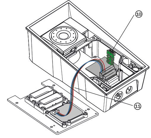
Mounting guide:
- Switch off the intercom.
- Remove the front panel (7) from the intercom.
- Mount antenna board (8). Use two enclosed self tapping screws (9).
- Plug enclosed cable (11) to the antenna board connector.
- Demount a button PCB (1). Don't disconnect its cable!
- There will stay four spacers after the switch board removal. Dismount the bottom right one.
- There are two short metal spacers enclosed to the reader. Take a longer one (5), 12 mm long. Screw it into the free hole.
- Plug an enclosed plastic support (6) to the reader board from the bottom side.
- Put the reader board (4) in the main board connector making sure that the mounting hole is directly above the spacer.
- Screw in a remaining metal spacer (3), 10.5 mm long.
- Fit the button PCB (1) back to its position using original bolts (2).
- If you want to use the tamper switch (to detect unauthorized opening the case, as a theft protection), insert the tamper board (10) in the connector located in the right-hand bottom part of the reader board (4). As the tamper switch shares the relay output (NO and NC) terminals, you cannot use the RELAY2 output with the tamper switch at the same time.
- Plug the antenna cable (11) to its connector at the reader board (4).
- Place front panel back and tighten all four screws.
|
|
|